Time to get the printers warmed up!!
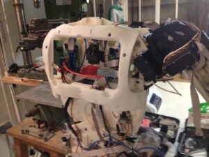
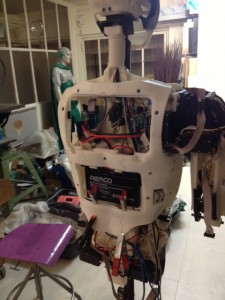
In this tutorial I will show you how to assemble the back covers. It is pretty easy if your prints are correctly printed without warping otherwise, you will have a hard time to join all the parts together.
Some of these parts require support during 3D printing, so please check the bellow list.
Download STL from the Gallery
Before printing all the parts you should print the CALIBRATOR, to check if your parts will fit together. If you have a very hard time putting those parts together, adjusting the horizontal expansion setting of your slicer software can solve that, this setting can vary depending of your slicer and printer but users report to set it at -0.15 is a great place to start.
An infill of 30%, wall thickness 2.5mm, best with no raft, no support(unless specified), use a brim for big parts to avoid warping.
Here is the list of parts and the number of prints needed for the back:
- 1x BackClaviHolder (add support)
- 1x BackCoverBottomLeft (add support)
- 1x BackCoverBottomRight (add support)
- 1x BackCoverBottomMid (add support)
- 1x BackCoverTopLeft (add support)
- 1x BackCoverTopRight (add support)
- 1x BackCoverTopMid (add support)
- 1x BackCoverLowLeft (add support)
- 1x BackCoverLowRight (add support)
- 1x BackHipsLeft (add support)
- 1x BackHipsRight (add support)
- 1x BackHipsMid (add support)
- 1x BackHolderCenterLeft
- 1x BackHolderCenterRight
- 1x BackHolderCenter
- 1x BackHolderLowLeft
- 1x BackHolderLowRight
- 1x BackSideHolderLeft
- 1x BackSideHolderRight
- 1x BatteryHolderLeft
- 1x BatteryHolderRight
- 2xBatteryPusher
- 1x BackDoorRight
- 1x BackDoorLeft
- 1x BackDoorClip
- 1x BackPower
Step1:
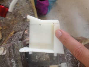
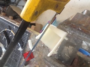
Trim all the support off your prints and make them all clean!
If you plan to use extra servos for the neck (Bob Houston upgrade) You will need to rotate upside down your Arduino and Nervo boards, mainly because the USB cable is not well positionned.
If you don’t plan to use the servo upgrade, you can start by adding and gluing all the holders to the torso plates.
You might want to check the 3D sketchs to see what part goes where!
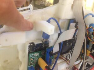
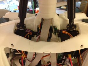
These small parts should be glued. Nota: the files you have printed will look different because I updated them to allow the set up for extra neck servos.
The middle should also be glued. If your parts are printed in ABS, you can use acetone.
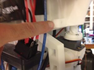
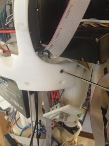
Same thing here for the low holder, Use glue or Acetone
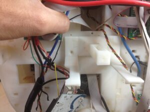
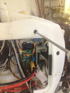
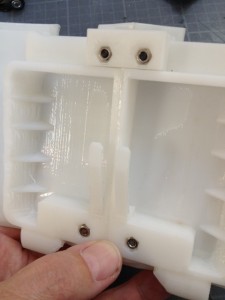
You need to add screws to fix the center holders. But it also can be glued.
Step 2:
It is better to assemble the parts directly on site to avoid deformations during the time it dries out. Use some clamps to glue and hold the parts together, this will seriously help to make proper fittings.
Add the screws and bolts to fix all the parts together.
Keep on adding more parts, these should NOT be glued, because it allows you to keep access if ever you want to modify things behind the switchs.
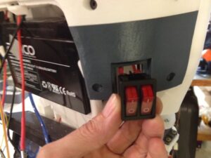
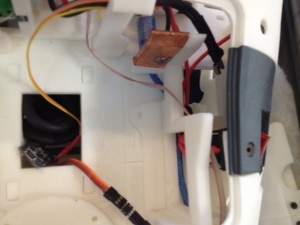
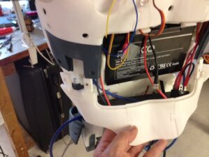
You have the option to add 2 switches on each side of the robot for various purposes. I use one as main shut down., another one is to power up the mini Amplifier. The third is to power up the wheel mobile base and the fourth is currently vacant. These switches are available in most spare electrical stores and on internet of course.
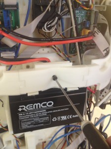
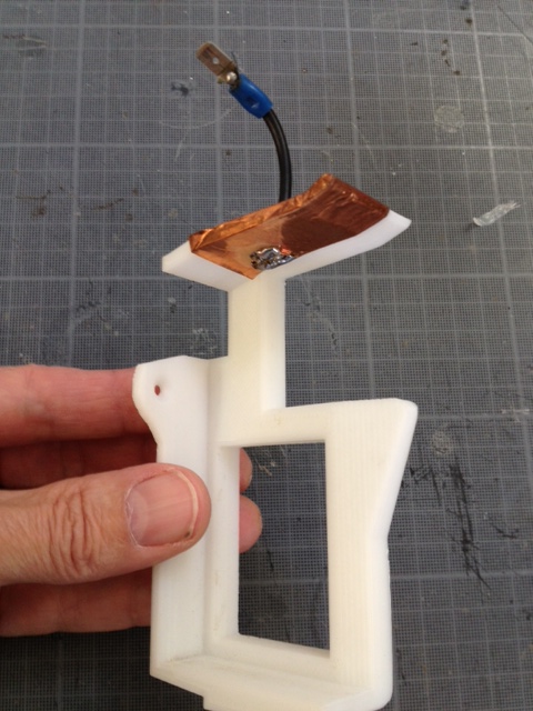
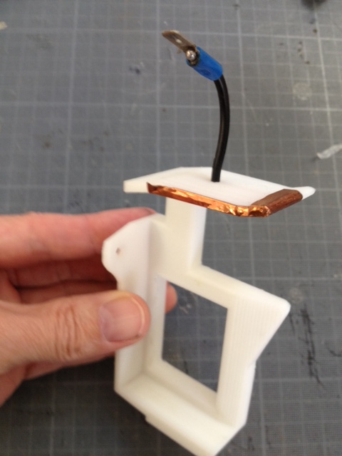
If you had already printed the Battery holders of the previous version, you can saw them or re print my new version. The new version of Battery Holders allows you to add a copper sheet on the top where the battery slides. Therefore when pushing the battery into the back, it can automatically give the power without having to connect wires everytime you switch battery.
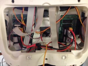
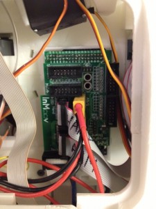
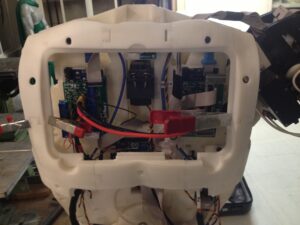
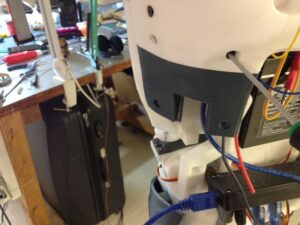
I fixed my USB hub on the bottom of the back. You can see it is a 8 port HUB USB3.0. Somebody made a nice fix to hold the USB hub in the back of InMoov here.
On the right side (blue) it is my USB Soundcard. On the top left, hanging,(in red) there is the audio jack that goes from the mini Amplifier to the USB Soundcard.
Now you can add the bottom part of the back. Again, I recommend gluing the parts on site to avoid deformations.
Glue the Battery Pusher inside the back door.
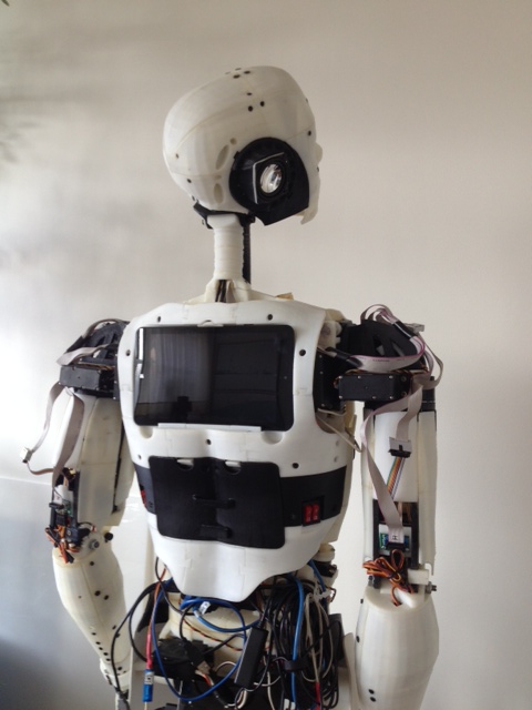
Connect the mini USB OTG cable to your Thinkpad Lenovo 8″ Tablet (see BOM for part list) and place and press fit on the back of your InMoov.
You might notice that there is no gap to connect the audio output, the reason is because I’m using a USB soundcard 3.0 which allows me to send the audio to the mini Amplifier. The USB soundcard also has an microphone input, which is handy in some environments. So all sound is treated through USB.
Check for the Upload & Update page in the gallery.
Have fun and be kind to your InMoov!!
Merci Gaël … super génial
Encore un peu de plastique à imprimer!!
Sir it’s hard to see the wiring of all the parts, could you please make a wiring sketch
Hello,
you can find a wiring sketch here:
http://inmoov.fr/wp-content/uploads/2013/12/Map-ConnectionsV2-719×1024.jpg
thank you sir
Thank you, Gael! Looks very very nice!!
You are welcome!
Are u using these MG996r for the side piston (bob houston) ? thanks
No I’m using two HK15298B, one as master and the other as a slave. Same technique connection I used for the Top Stomach servos.
Hi Gael,
why not using a simple Y connection between the two servos? Instead of modify them in the master/slave configuration?
It will require to miror one piston, but it seem too simple, I probably miss something
Yes it is possible to do as you suggest but note that sometimes servos do not move precisely at the same speed which creates a counter force on each one of them.
Hi Gael,
nearly finished the back now. i bought another printer so have 2 now – much quicker!.
the switches where dis you source them from. i want to get the same so i know they fit.
thank you
Didn’t I put the link on the tutorial page? I bought a bunch of ten on Aliexpress for a very low price.
Do you know the model number of your Lenovo tablet ?If so would you mind sharing that info ?
Hello,
You can refer to the hardware and BOM page to have the references of the tablet.
Dear Gael sir, Its essential to use Lenovo think pad?
THe space reserved is designed for that tablet. But you might find another type of tablet that can also fit. It’s important to have a tablet with a system that can run MyRobotLab to process InMoov.
Yeah You are right sir, I have a problem. Tablet is connected to USB port 3.0 or others ? And where is the kinect connected? (Also to USB port?)
As described in the Hardware and BOM page, you need a USB OTG cable which can also supply power to the tablet and also connect a USB Hub.
All USB devices (Arduino, Kinect camera, headphones..) are connected to the prescribed Hub 3.0. To be autonomous you will also need an extra powerbank (10000mAh) and a a power supply for your hub which can deliver at least 4Amps.
Remember each USB devices consumption is about 500mAh. If your Hub doesn’t get enough power, the USB will disconnect and reboot all the time.
Hi Gael,
I am in the process of buying battery and hub.
I read in the Forum that a 2.0 Hama self powered(i.e. drawing power from the tablet USB port) hub should do.
Here, on the contrary, you talk of a 3.0 4 A hub and of an extra powerbank .I understand that both tablet (I am planning to use a Windows 10 Asus tablet I already own) and hub should be connected to the power supply by an USB OTG cable.Which power supply should I then use? The 6 V 12 Ah battery would be sufficient or you mean that I need add another 10 Ah battery? If so ,where should I place it?
As you see, I am pretty much confused. Your valuable help would be most welcome. Thanks a lot and best regards
Andrea
Hello,
Consider the hama hub as a very old post.
Its better to use the USB hub 3.0 with 8 ports specified in the Hardware and BOM page.
The goal of the OTG is to power the tablet and to allow the connection of devices(arduino) to the unique USB port of the Lenovo tablet.
If your ASUS tablet has more than one USB port, it might be easier for you and an OTG might not be necessary.
The 6V12AH is to power the servos.(although it is also possible to reduce the voltage to get 5V for to power the hub and the tablet)
The powerbank is used to power the hub and the tablet.(this is in case you want an autonomous robot)
The power supply 6V60AH can replace both(the battery 6V12AH and the powerbank), but the robot is not autonomous, and needs to be connected to a wall outlet.
I hope this helps.
Very well, Gael.I had missed the meaning of powerbank, which I might consider later on. For the time being , I will use a 6v 12Ah battery and power an 8 port hub through a simple circuit made around an IC 7805, as my tablet has only one USB port.I just hope the battery could have a charge that lasts a reasonable time.
However, it seems that an 8 port 3.0 hub is very difficult to find, if not impossible (7 and 10 are , on the contrary, readily available,as 2.0 8 port also are .Do I absolutely need (considering the future) 8 ports or 7 might do? (a 10 port is 20 cm long and might not fit.)
What do you thinK?
Thank you again and best regards
Andrea
Here is the link to the hub I’m using:
http://www.aliexpress.com/item/Adroit-8-Port-High-Speed-USB-3-0-Hub-Power-Adapter-for-PC-Laptop-Computer-JAN15/32596302388.html?spm=2114.30010308.3.71.QxI2Pz&ws_ab_test=searchweb201556_0,searchweb201602_4_10037_10017_507_10033_10032_401,searchweb201603_2&btsid=85082c1b-cfbe-4be8-8b5b-f035c6e52baa
You can use the attaching 3d parts from here:
https://www.thingiverse.com/thing:2216414
Ciao andrea,anche io possiedo un tablet asus. Hai stampato un alloggio per la schiena di Inmoov? La condivideresti?
Grazie
Hi Gael,
An update on releasing the stl, for the battery cover plate?
Cheers
Chris.
I was planning to work on it during this summer, but I ended up fixing the cheminee on the roof of my house…
That is the update.
First things first.
Thanks Gael,
Yes of course house come first!
Did you get it fixed?
Chris.
Sorry that was meant to say: “Any” update
Cheers,
Chris.
ok,
Quick and late update on this post.
Back door battery STL is now available in the galery for STL.
Dear Gael sir, I’m making this robot for extracurricular activity to get into top universities in the US/UK/CND/AUS/NZL. What’s the uses of this robot?
The robot can be used for many things, but I developp it mainly to be an educational robotic platform. If you look at videos of InMoov, you find many applications, like prosthetics, house cleaning, bar tender, telepresence in hospitals.
Remember that InMoov design is under a CC-BY-NC license.
Best,
Thank you Gael sir, for giving me more information about InMoov robot. Thank you very much…
Hi Gael!!!!!
Congratulation, is amazing… im bulding the second inmoov but i have a questions, can you recomend alternatives to the Tablet, now i have problems to buy that, and need recomendation to big servos, any recomendation to buy anothers more cheap if not I will have to save to buy the recommended. and finish THE LEGS, i can not wait… its a joke, jajaja thanks gael and receive my congratulations
I haven’t found a replacement tablet yet…
If you find one, let me know, it will be helpfull for others as well.
For other servos, I recommand you look at the “Hardware and BOM” page where I listed other possible servos.
FYI, I’m not sure how good this idea is, but I intend putting a couple Raspberry Pi’s inside my InMoov, and then using a VNC Remote Desktop from iPad, laptop, etc to access control. The Pi can run MRL for me, and it means that my access to control functions is not tied to poking InMoov in the back.
It also means that I will need to create a cover in place of your tablet, as an access panel to the electronics.
The covers in place of the tablet are available on Thingiverse. Search InMoov collection.
Sure having a Raspi works, I personnaly use the tablet because it is a complete solution, with screen, keyboard, sound, bluetooth, wifi etc. I almost never poke in the back of InMoov because it isn’t very handy. I use TeamViewer or even the remote solution within MRL.
Search on MRL, there is tutorials for to use the Raspi with MRL. Make sure to use a Pi3 because the Arm processor is not very good at processing fps video under OpenCV.
Hello Gael! I’m almost done with the robot , but I don’t know how to wire it with the switches and the battery. Can you post pictures or something so Me and other inmoov builders can wire out robots correctly. Thank you
Where do you connect the X-box kinect?
In the USB hub.
In the USB Hub. Power supply has to be plugged in outlet unfortunately. There is possibility to transform it to be powered with a 12V battery also. You need to search internet.
bonjour merci pour ce super montage je suis a mes essais avec mon imprimante après quelque problèmes j’ai de bon résulta après le réglage de la tentions des CI j’ai trouver un ventilateur pour pc portable a super prix que j’ai mis pour refroidir les CI un bon montage merci
un grandísimo trabajo, espectacular, yo llevo un 60% impreso y cuanto mas lo miro mas me asombra. Soy fan tuyo. Un gran abrazo desde España
Thanks a lot for your comment!
What thickness of copper foil is best for the battery connectors? 0.1mm – 0.5mm?
Hello,
Both should work, although I used 0.1mm thickness.
Hello Gael!
In terms of the size of the nervo board, I want to know its exact size of it , to know the possibility of delivery by express shipping
hi Gael,
still waiting for the nervoboard, when it is in the shop back?
Regards Detlef
Hello,
The shop has re-opened today 02/07/20.
Bonjour Gael,
Aujourd’hui nous avons reçu les 2 sets commandés en bon état, pour lesquels nous vous remercions,
bonne journée,
Jo
Parfait!
Bonne soudures et programmation!
Hi,
I’ve issues of power I think. I’m using a Chuwi larkbox as main computer, and when starting my Inmoov it’s crashing during initialization and I’ve on the Windows a message of missing resources. I use kind of USB 3.0 Hub 7 ports described here, powered by 5V. I connected to an external power supply to check the current consumption of it, but remains at 0,2A. Were there already people facing this issue? I guess it’s a problem of the USB Hub and not of the computer USB capabilities… Any advice is welcome.
Hello,
If you have 2 arduino + one camera and maybe more connected to the hub, its power supply should be able to deliver at least 4 Amps.
This is related to the surge of power required by the servo motors at the initialization.
I wouldn’t be able to explain why, but I noticed that if there is not enough power for the hub, the extra power required at peak tries to draw from the power of USB tablet causing a crash.
As a test, you could try to launch with less servo connected and only one arduino connected to the hub. If all starts fine, the problem is probably the Hub power supply that needs to be able to deliver more Amps.
Bonjours a tous, je suis entrain de faire le torse et l’arrières et je vais attendre pour faire les bras, mains, la tête est terminée (pour les yeux j’ai mis que une camera mais pas les webcam conseiller, il faut que je rachètes des servos moteurs car je les ais alimenté avec du 12 volt, je crois que je les ais cramé).
Cependant je me pose une question pour brancher tout les servos moteurs avec une alimentation autre que l’alimentation de la carte arduino comment avez vous fais ? (Vous avez mis un bornier ?) .
Par avance merci de vos réponse.
Ludwig
Ludwig désolé correction auto.
Bonjour,
L’alimentation directement aux nervoboards qui redistribue aux servo moteurs.
Je conseille d’intercaler un interrupteur entre l’alimentation et les nervoboards. Vous trouverez tout le schéma de connection sur la page « Hardware and Bom »
ok merci je vais regarder ca du plus près
bonjour enfaite si j’ai bien compris les alimentation des servos sont sur les nervoboards, j’ai plus qu’a trouver des nappes. Encore Merci
Hello,
Effectivement, votre alimentation (6V50Ah) sera connectée au XT60 (connecteur jaune) sur les Nervoboards. Ensuite les Nervoboards redistribuent sur chaque servo moteur.