Download STL files from the Gallery.
Before printing all the parts you should print the CALIBRATOR, to check if your parts will fit together. If you have a very hard time putting those parts together, adjusting the horizontal expansion setting of your slicer software can solve that, this setting can vary depending of your slicer and printer but users report to set it at -0.15 is a great place to start.
The size of the molds are big and require a big print area. Check if it fits your printer prior starting building the head. Standard 220x220mm bed size will do the job. I printed mine at 0.4mm because a primer filler is then applied on all surfaces. I am using Upol UHS high build Primer S 2021 G/I with it’s fast hardener S 2021/I. You can use Primer filler in spray can, make a test to check if the silicone reacts well against the primer you found.
The silicon reference is Smooth-On Ecoflex 00-10. One skin requires about 500/600Gr. You can color silicon with oil paint or pigments. You can also add flocking to give it a skin touch. Because skin color is very light and slightly transparent, you only need to add a very little amount. Mainly white, then some red and a tiny bit of yellow.
It is mandatory to use a release agent such as wax spray prior casting. Type Alchemie R5.
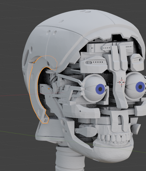
i2Head tutorial:
Here is the list of parts and the number of prints needed for the head:
-
- 1x BottomTeeth
- 1x CheekPuller
- 1x EarLock (add support)
- 1x EyebrowSupport
- 1x Eyebrow
- 1x FaceHolderLeft
- 1x FaceHolderRight
- 1x ForHeadSupport
- 1x ForHeads
- 1x GearHolder
- 1x JawHinge
- 1x JawPiston (add support)
- 1x JawSupport
- 1x Jaw
- 1x LowBack (compatible from original head)
- 1x MainGear (compatible from original head)
- 1x UpperLip
- 1x Ring (compatible from original head)
- 1x ServoGear (compatible from original head)
- 1x SkullServoFix
- 1x TeethTopHolder
- 1x TopBackskull (compatible from original head)
- 1x TopTeeth
- 1x TopskullFront
- 1x Topskull (compatible from original head)
- 1x servoAdapter (only if you use a smaller servo than HS805BB for to rotate the head)
- 1x servoHornAdapter (only if you use a smaller servo than HS805BB for to rotate the head)
Print with an infill of 30%, wall thickness 2mm, check for parts that needs support.
Assemble together MainGear and NeckPlateHigh with 4 screws (3mmx16mm).
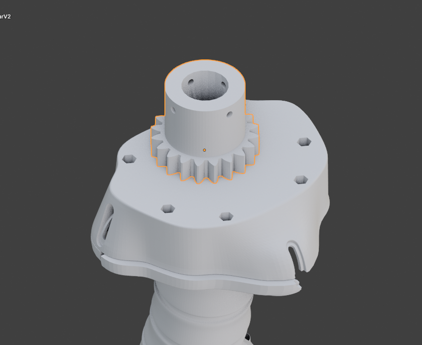
Add ServoGear on the top.
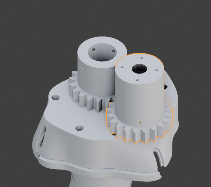
Slide over the GearHolder, make sure it can rotate freely in both directions.
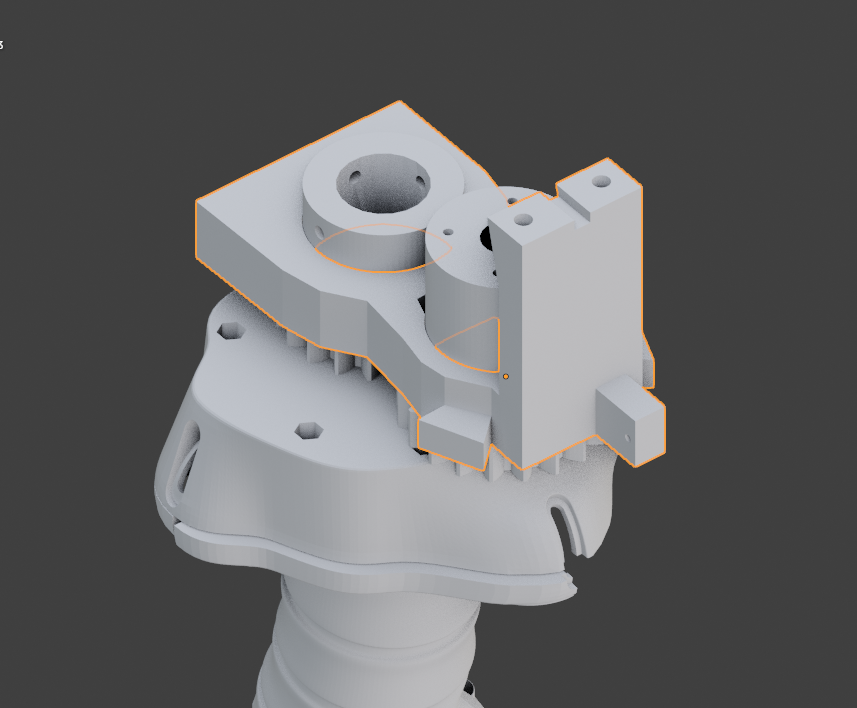
Glue together GearHolder, FaceHolderRight and FaceHolderLeft.
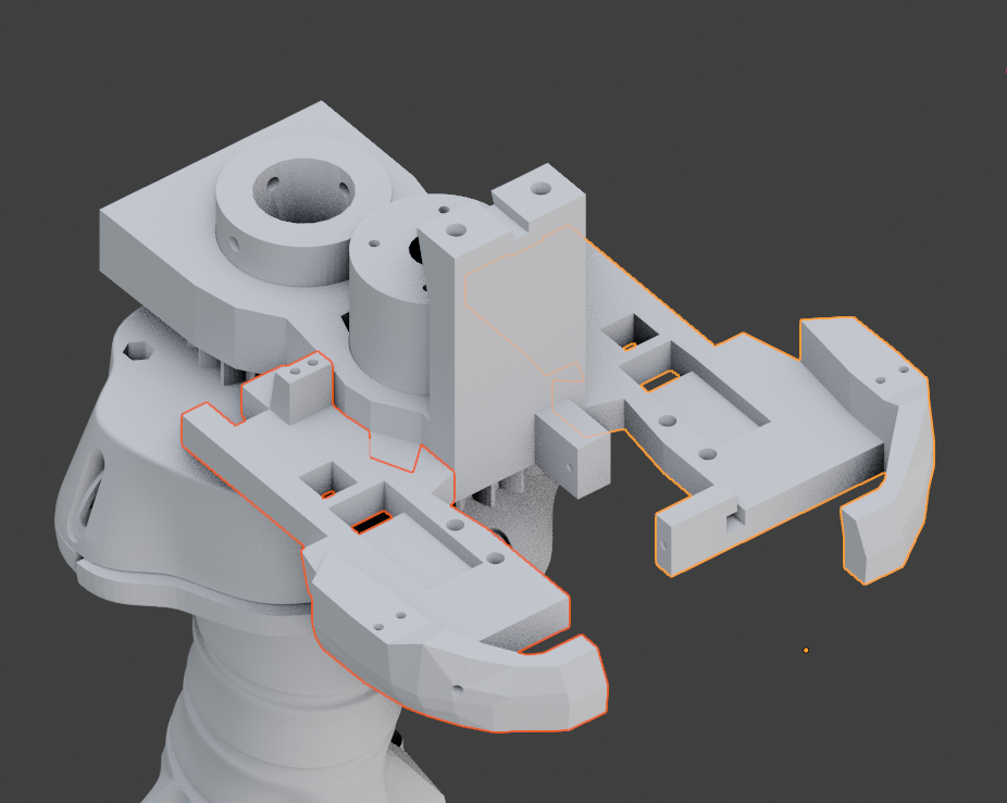
Press push in the two JawHinge. If it is too loose, glue them in.
Mount TeethTopHolder with 4 screws (3mmx16mm).
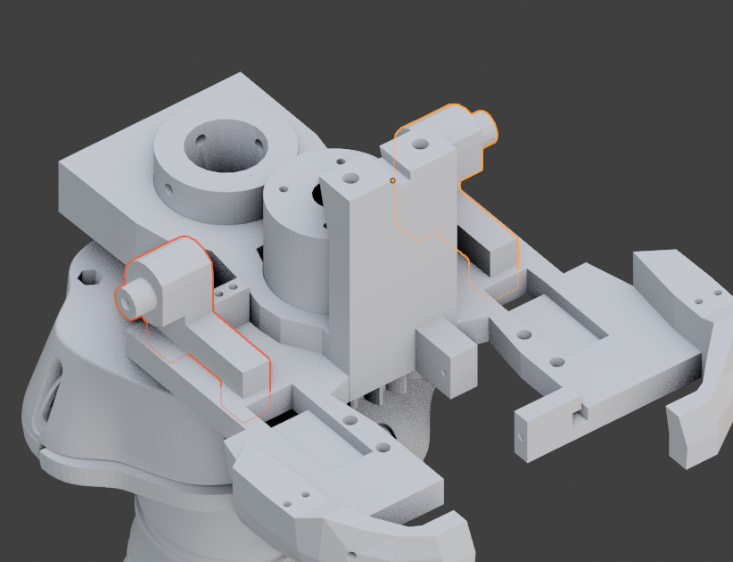
Set two servos with their horns and make sure they are preset at 90° in your software.(rest position)
Fix to the servo horns the two CheekPuller.
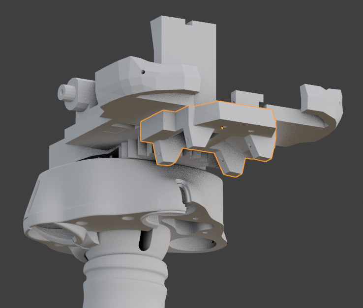
Assemble TopTeeth with two screws (3mmx20mm).
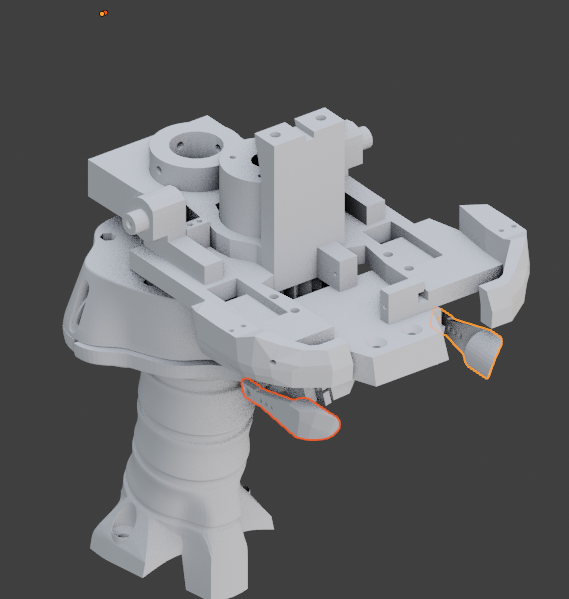
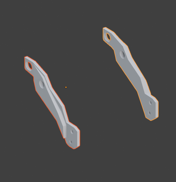
Get the two JawSupport.
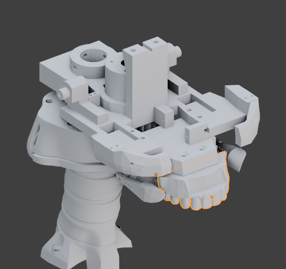
Fix the Jaw with 4 screws (3mmx10mm + bolts) or just glue the parts together.
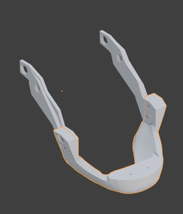
Mount with 2 screws BottomTeeth to Jaw. (3mmx16mm)
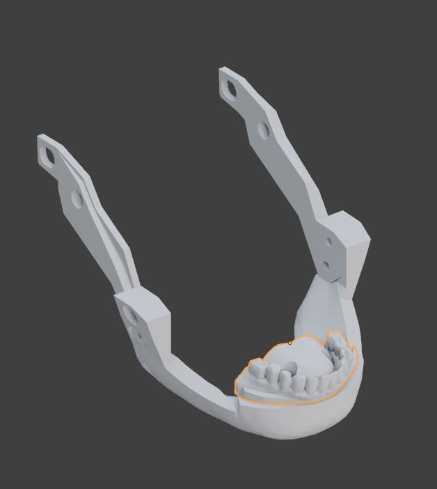
Clips the assembly on the JawHinge. It should move freely. The teeth should close nicely.
Add LowBack with two screws. (3mmx16mm)
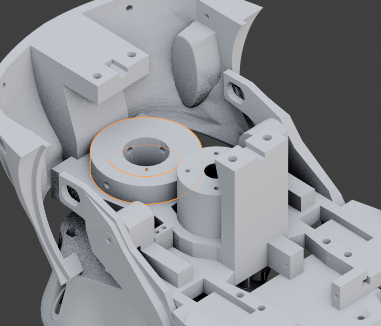
Press push the Ring making sure the holes align with the holes of MainGear. Add only 2 screws from the sides. (3mmx16mm)
If you have a HS805BB servo, preset the horn at 90% in your software. Add 2 screws ( small wood screws) between the horn and the ServoGear.
If you have a Smaller type servo (JX PDI 6221MG 180°), preset the horn at 90% in your software. You need to assemble it with the ServoAdapter and ServoHorn Adapter. Add 2 screws ( small wood screws) between the horn and the ServoGear.
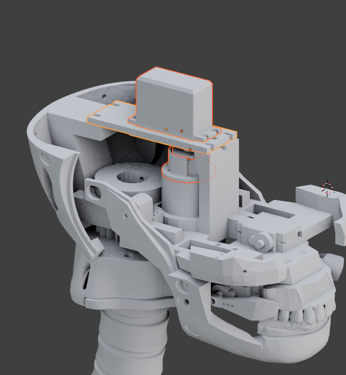
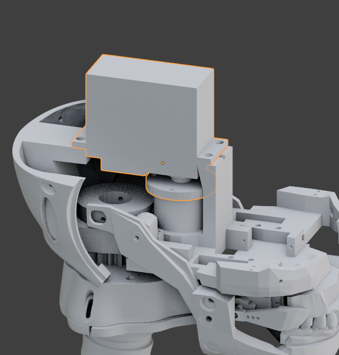
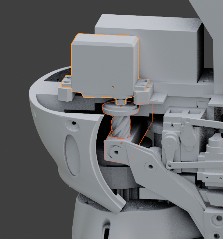
Press over the SkullServoFix. Use 4 screws (wood screws) and fix together the SkullServoFix, the servo and GearHolder.
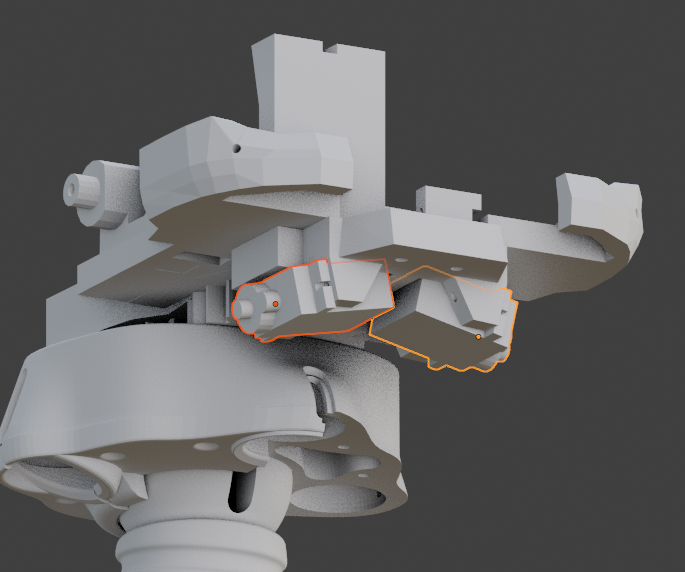
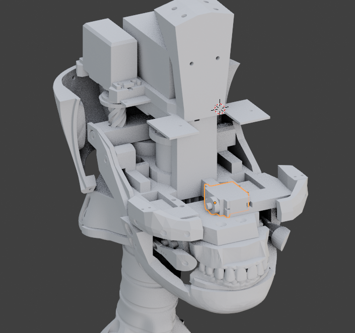
Mount the horn to your servo (JX PDI 6221MG 180°) and preset it at 90° in your software. Attach JawPiston with 4 screws. (small servo screws). Insert JawPiston into NoSupport. When the servo is going to rotate by software, it needs to be able to open and close the jaw.
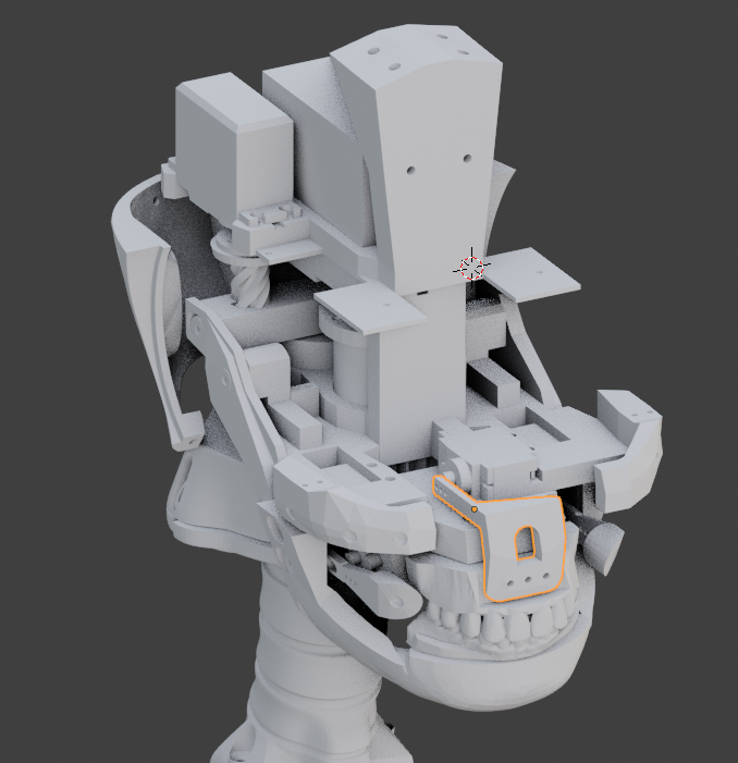
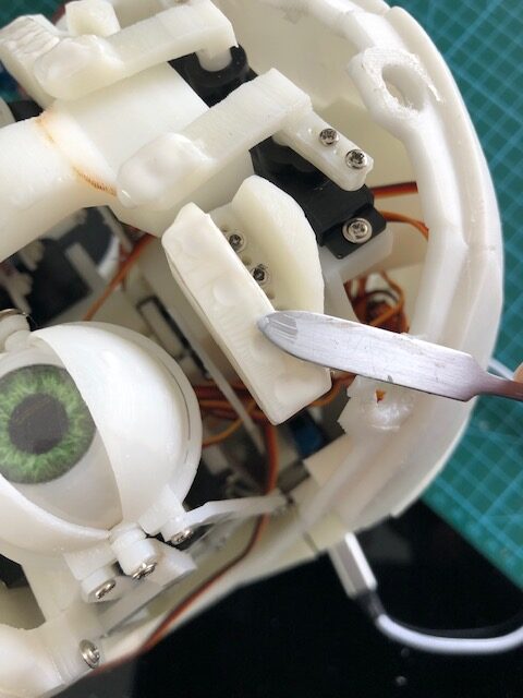
Add a servo as shown below with two screws (small servo screws). Make sure to preset the servo at 90° in your software and mount the horn.
Attach to the horn UpperLip with 2 screws (small servo screws).
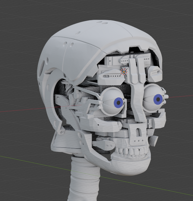
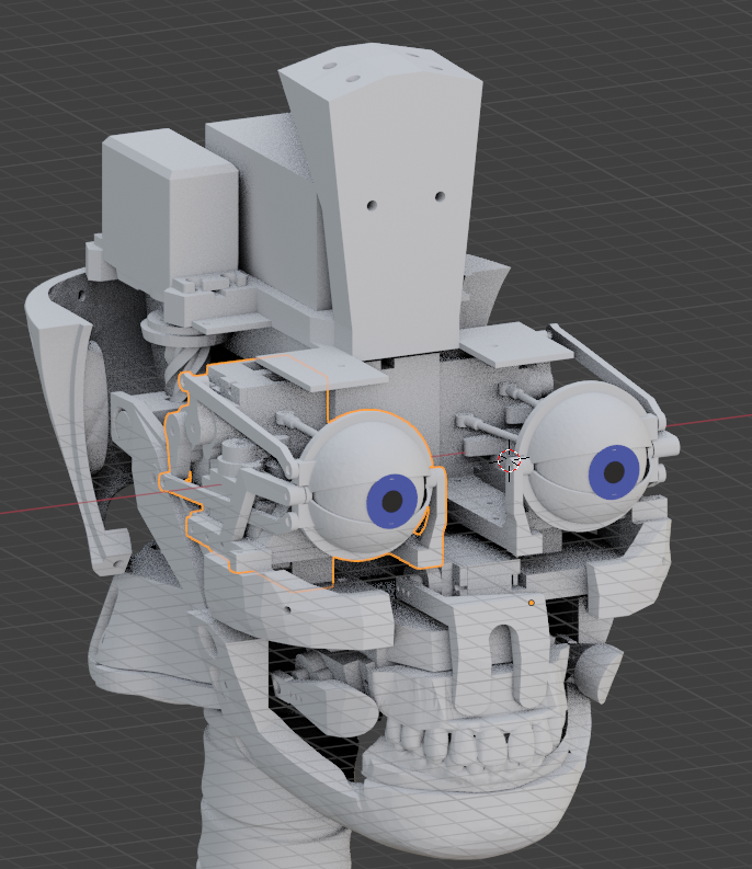
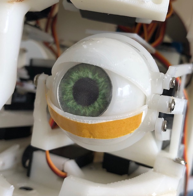
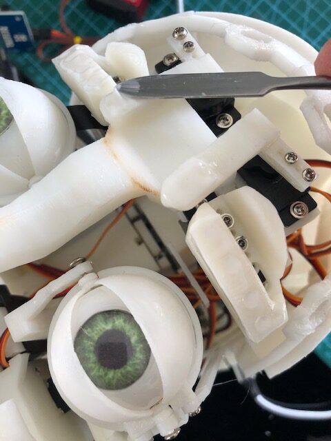
Add the left eye assembly. And fix it with 4 screws (small wood screws).
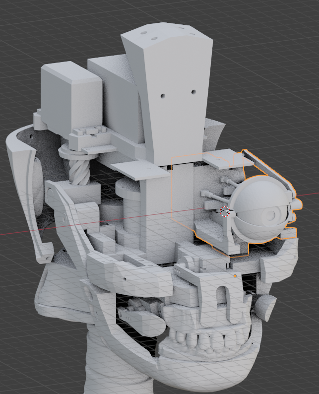
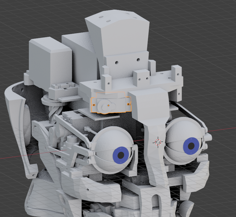
Add the right eye assembly. And fix it with 4 screws (small wood screws). You have a space above the eye assemblies to set the camera driver board with 2 small screws. Make sure to pass the camera ribbon (cable) between the eye and driver board and allows the eye to move freely.
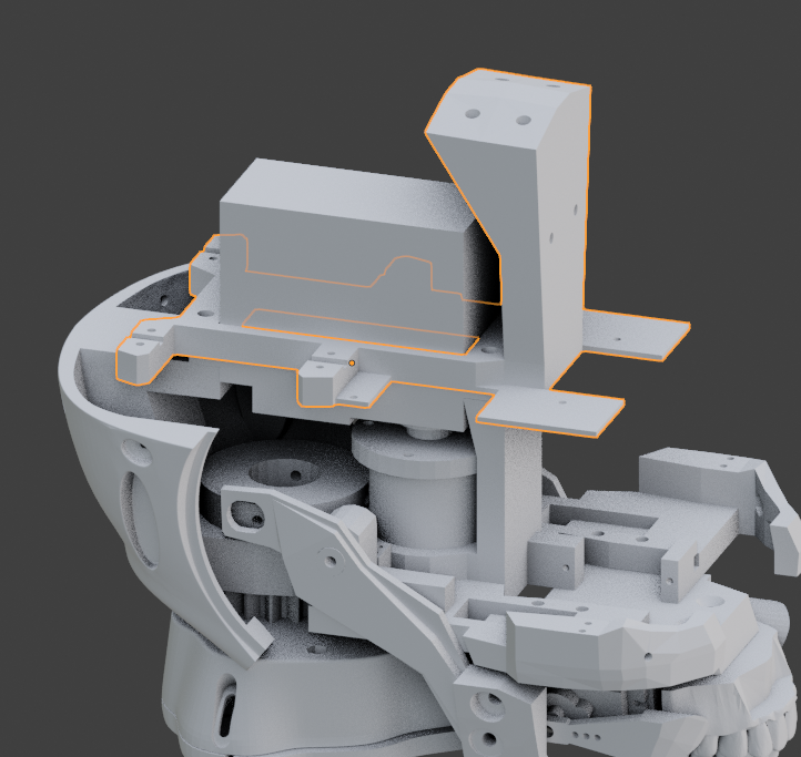
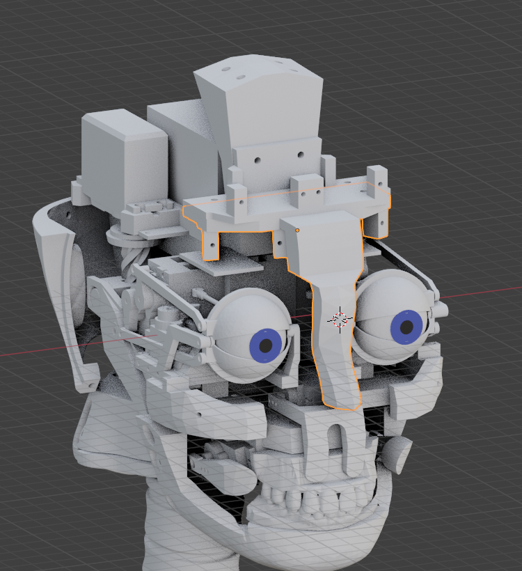
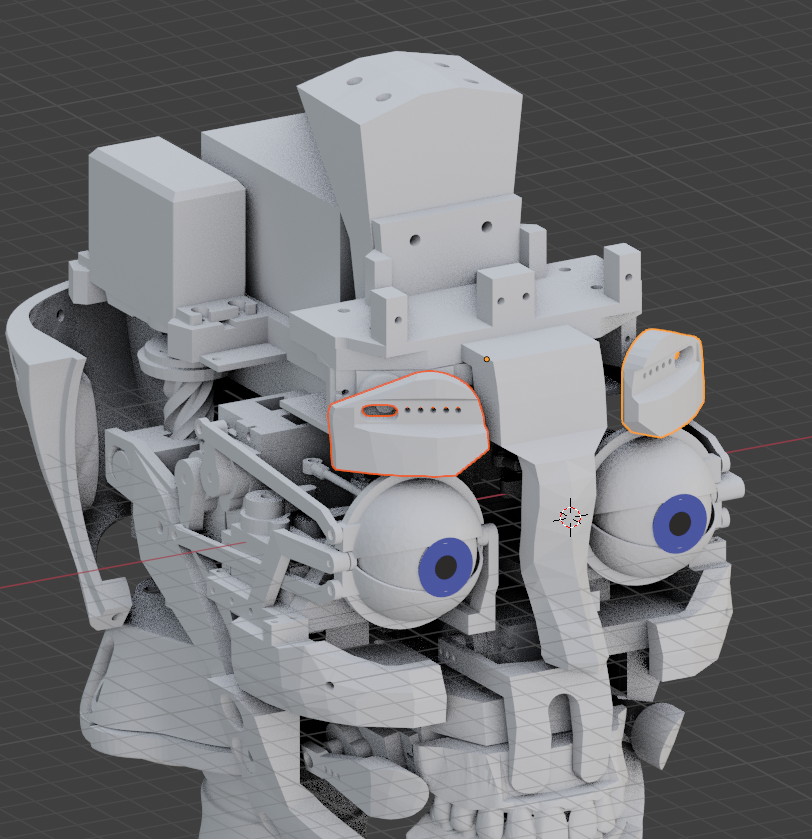
Add the ForHeadSupport with 2 screws (3mmx16mm).
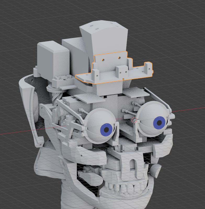
Glue or use 4 screws to mount EyeBrowSupport with ForHeadSupport.
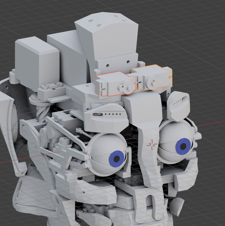
Add both servos for the eyeBrows with screws (small servo screws). Make sure to preset the servos at 90° in your software and mount the horns.
Fix each EyeBrow to the horns with respectively 2 screws. (small servo screws)
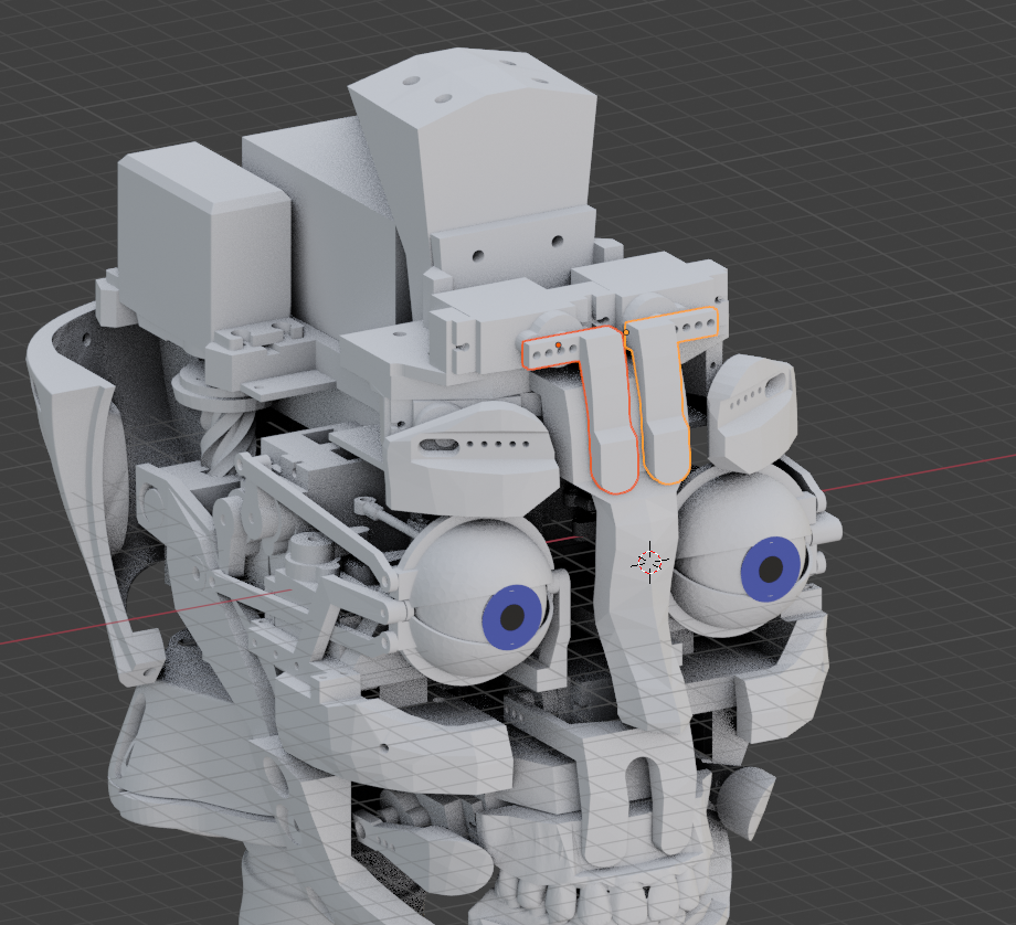
Add servos with screws to ForHeadSupport. Make sure to preset the servos at 90° in your software and mount the horns.
Fix each ForHead to the horns with respectively 2 screws. (small servo screws)
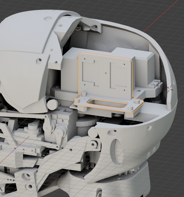
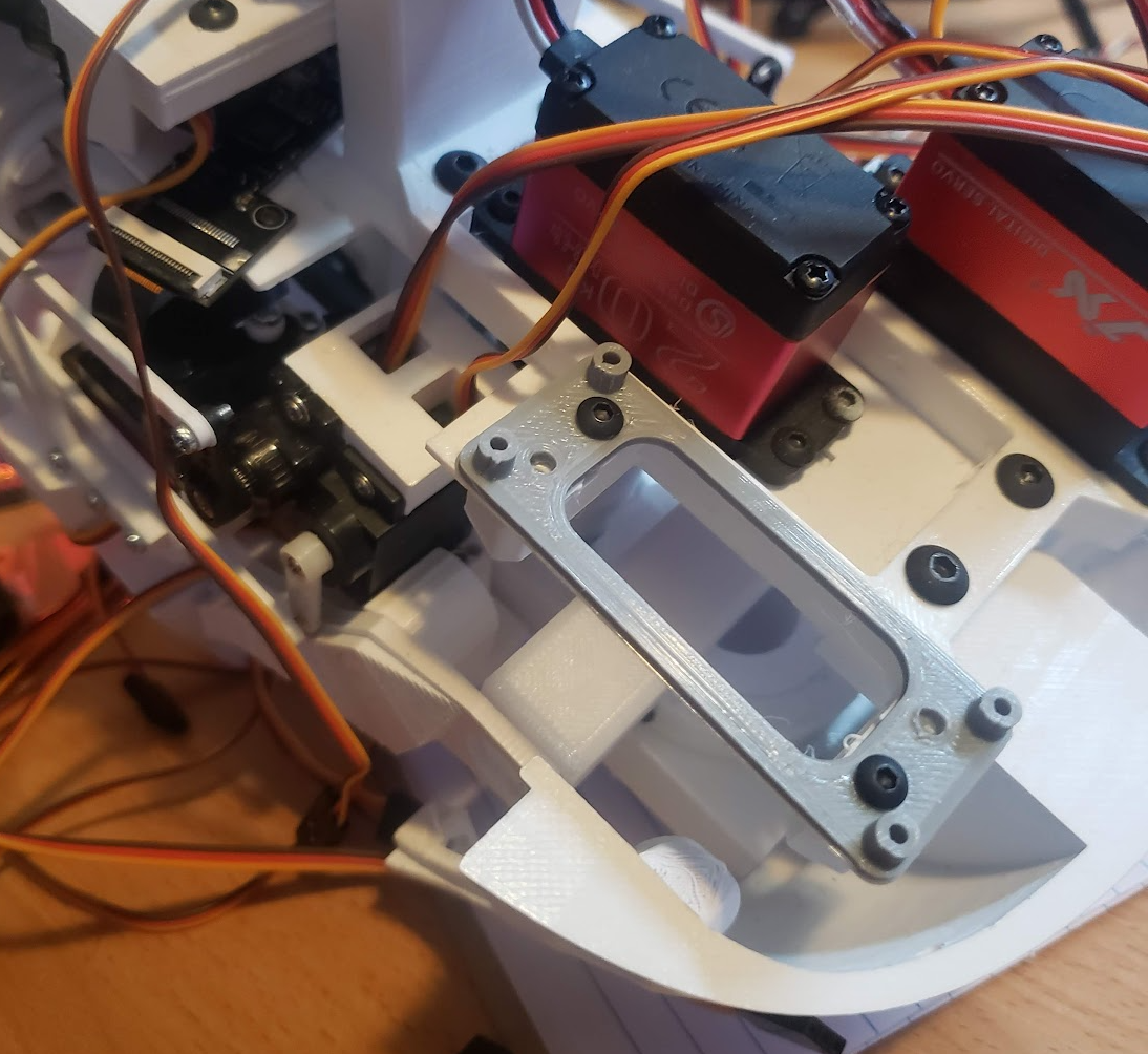
At this point, you might want to install and mount the PCA9685 board with it’s support, and the two mini breakout Nervoboards. (eye mouth)
You can start connecting the servo pins according to this excel sheet: Pin number connection
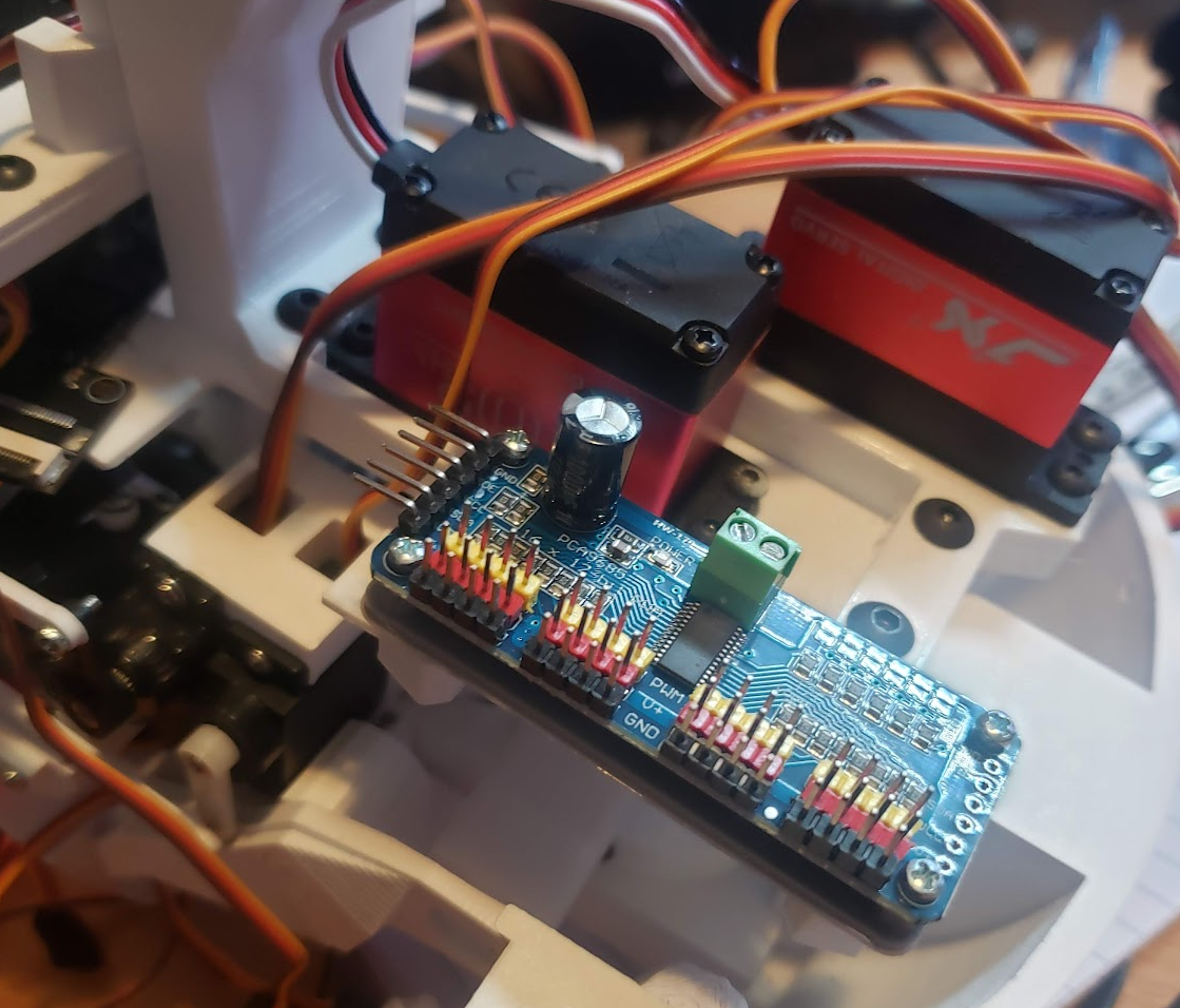
The PCA9685 is directly connected to the i2C pins on the left Nervoboard. Use the 5V pin as shown bellow. Respect the polarity and pin numbers. You can power the PCA9685 servo connector with one of the power source XT60. I used the same ribbon cables for the pin connections as for the mini breakout boards and used some 12 gauge wires for the power connection.
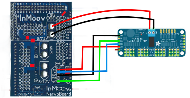
If you are not using a Nervoboard, here are the way to connect your PCA9685:
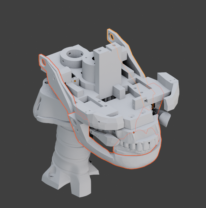
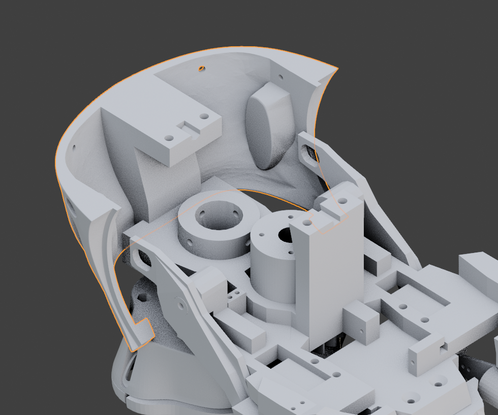
Mount the 2 TopBackSkull respectively with 2 screws (3mmx16mm).It is best to add bolts on the inner side of TopBackSkull. I heat up the bolts with a small flame and press it with pliers into the bolt cavity, making sure it cannot fall out.
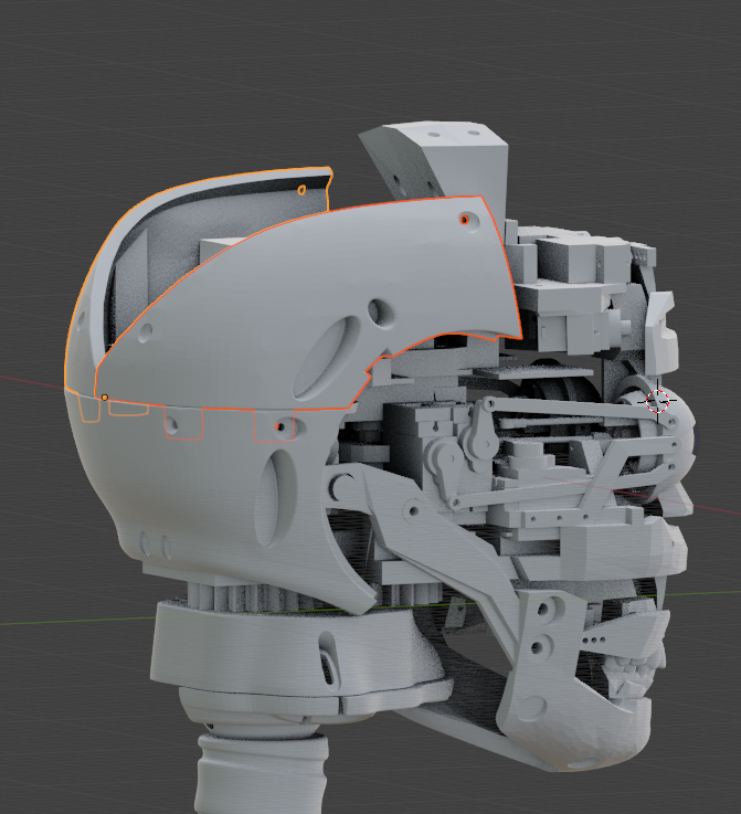
Same process for TopSkull. The 2 top screws are (4mmx20mm)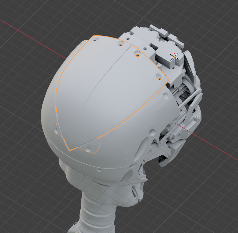
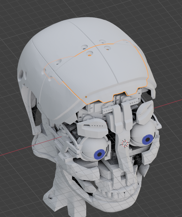
Same process for TopSkullFront.
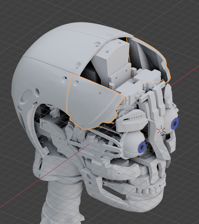
Same process for TopSkullFront.
Add EarLock on both sides respectively with a screw (3mmx16mm).
Note that the i2Eyes are synced to the original eyeX and eyeY.
Also the i2Eyelids are synced to the original eyelids servos.
This will probably change in the future, but for now it allows to use standard gestures to operate the i2Eyes and i2Eyelids.
Here is the listed names for the new servos:
## the eyes
i01_head_eyeLeftUD
i01_head_eyeLeftLR
i01_head_eyeRightUD
i01_head_eyeRightLR
## the eyelids
i01_head_eyelidLeftUpper
i01_head_eyelidLeftLower
i01_head_eyelidRightUpper
i01_head_eyelidRightLower
## the eyebrows
i01_head_eyebrowRight
i01_head_eyebrowLeft
## the cheeks
i01_head_cheekRight
i01_head_cheekLeft
## the upper lip
i01_head_upperLip
## the for head
i01_head_forheadRight
i01_head_forheadLeft
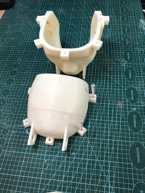
i2Head molds tutorial:
I printed mine at 0.4mm and used an old BFB 3D printer, this is the reason my mold looks awful, but then I applied sprayed car filler plus some sanding and finished with a clean car filler spray. Even if your prints looks clean, you should use car filler. Silicone is so thin, it can pass through the surfaces of your prints. As a result you wouldn’t have enough of 500/600Gr of silicone.
It is mandatory to use a release agent such as wax spray prior casting.
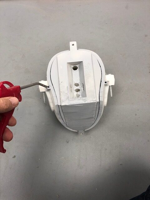
The three inner molds should not be glued or attached to each other, otherwise you will not be able to release the skin and inner molds from the outer molds.
The purpose of the angled middle inner mold is to be able to slide out easier once the silicone is cured.
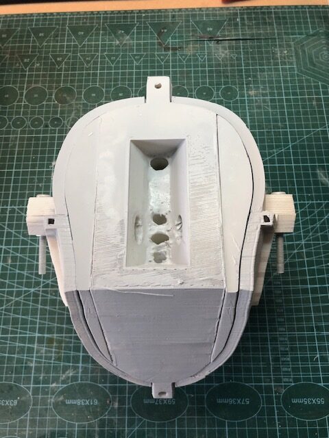
Attach the two outer molds together with bolts. Normally, this won’t be detached anymore. The bolts help for the alignment.
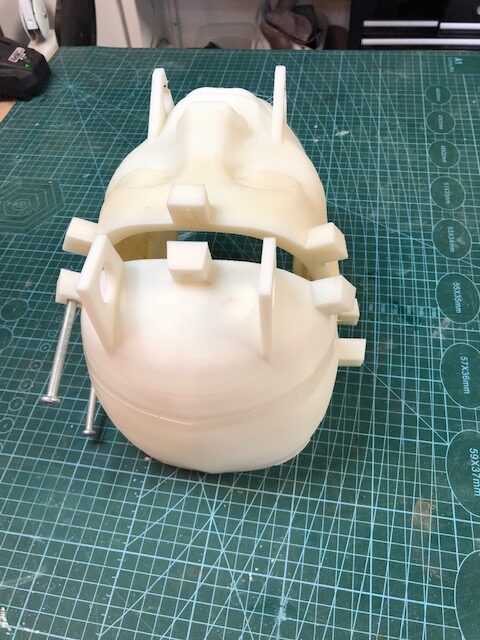
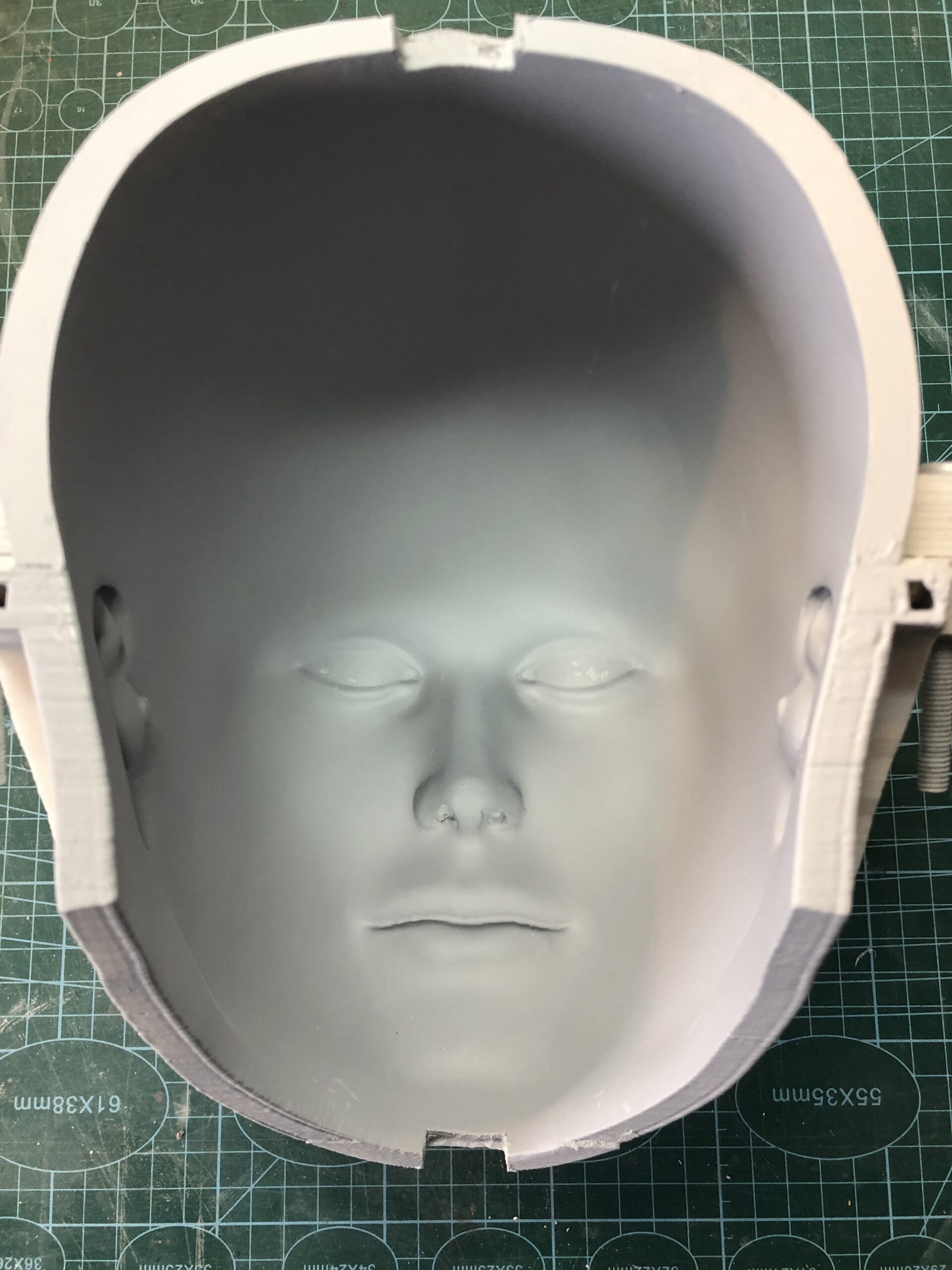
Use car filler to fill the gap between the two parts. This separation line should not be visible afterwards. I used heavy grain sand paper to do this.
If your mold is clean you can use grain 400. I had to go first with grain 80->sprayed car filler->grain 150->sprayed car filler->grain 400->sprayed a last layer of car filler from far to create a grainy skin effect.
I use polyurethane car filler Primer from Upol, but most users won’t have a compressor with air gun, so using car filler in spray can is another option.
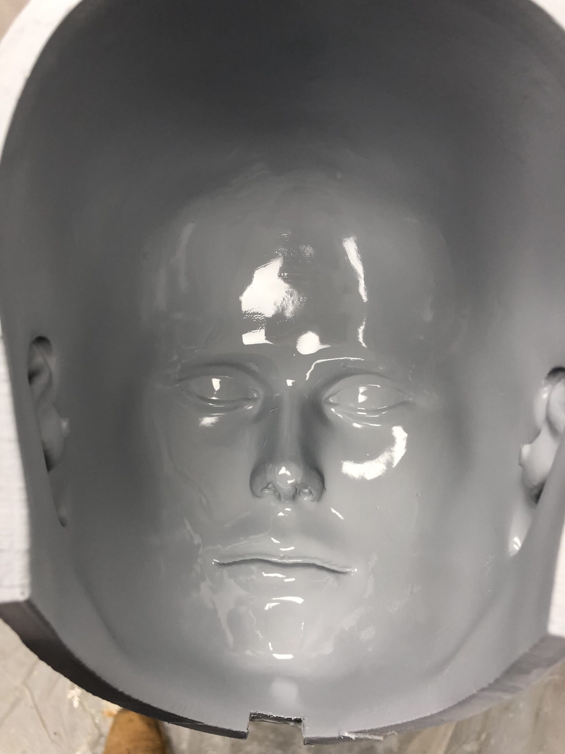
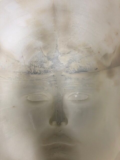
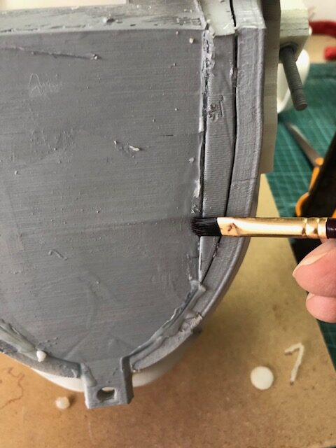
This is the finished mold with the skin grain effect sprayed from about 60 cm distance. The filler is kind of dry when it reaches the surface of the mold but still adheres.
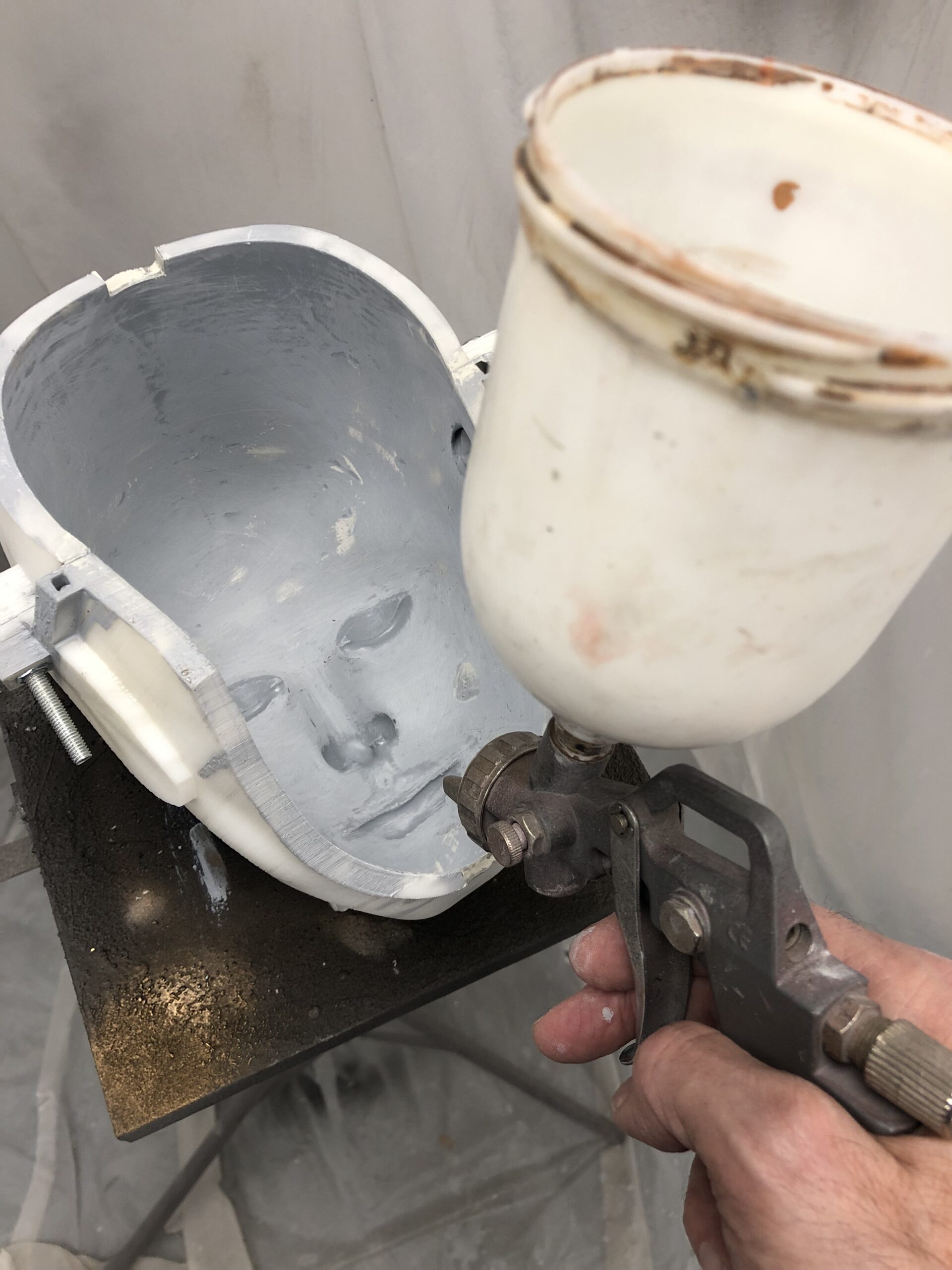
Spray also with car filler the inner molds, this is mandatory to help for de-molding and mainly avoids any silicone to go through your printed parts.
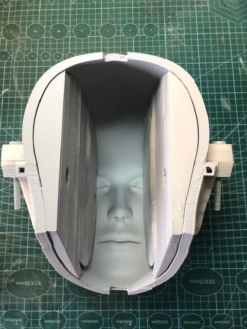
The purpose of the angled middle inner mold is to be able to slide out easier once the silicone is cured, and to press down the two side inner molds. It is mandatory to use a release agent such as wax spray prior casting. Spray with the release agent all surfaces of the molds.
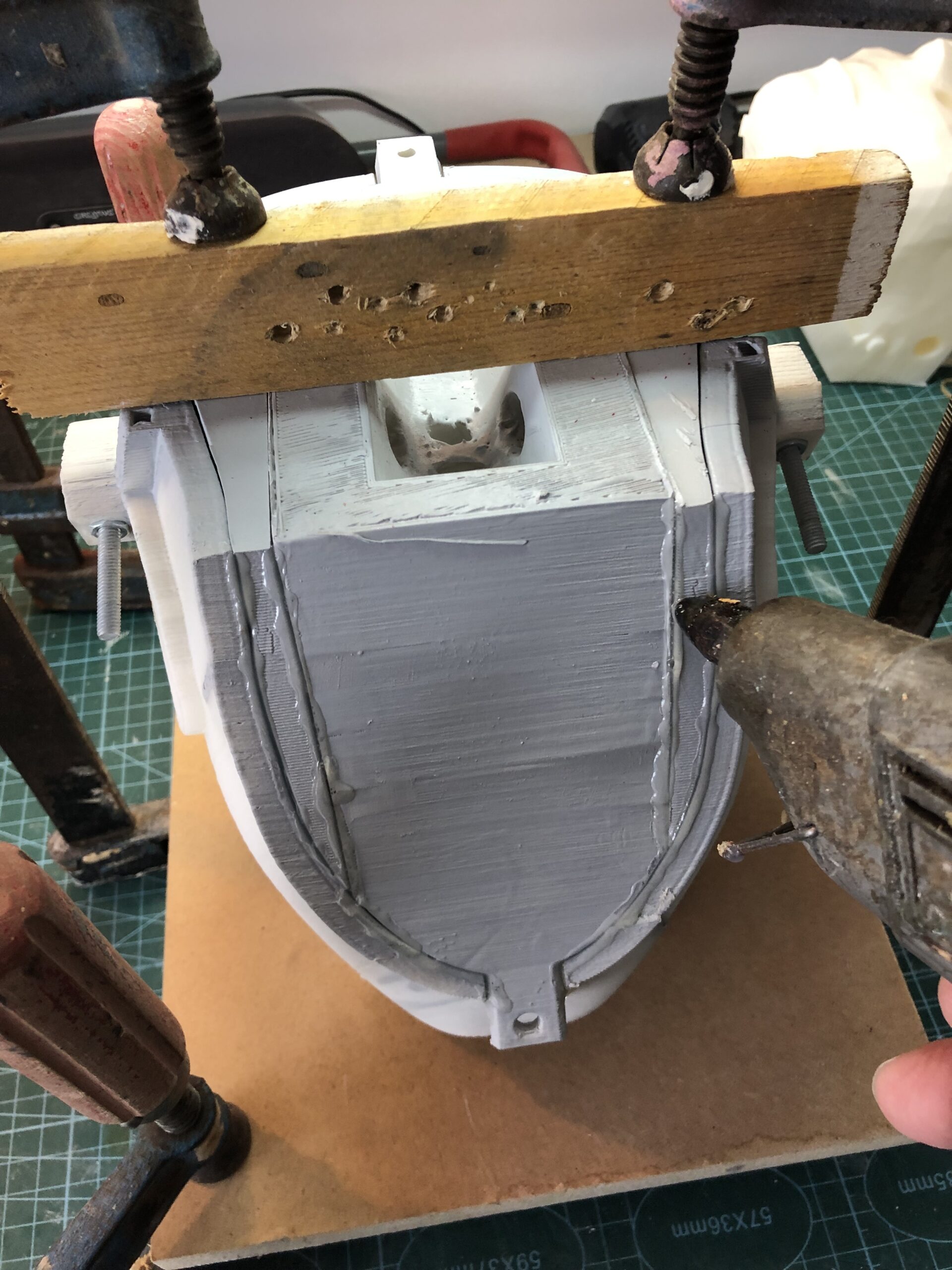
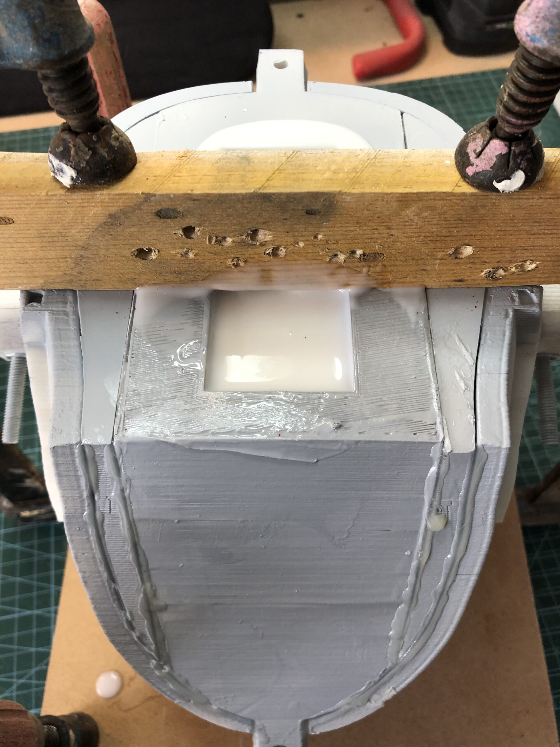
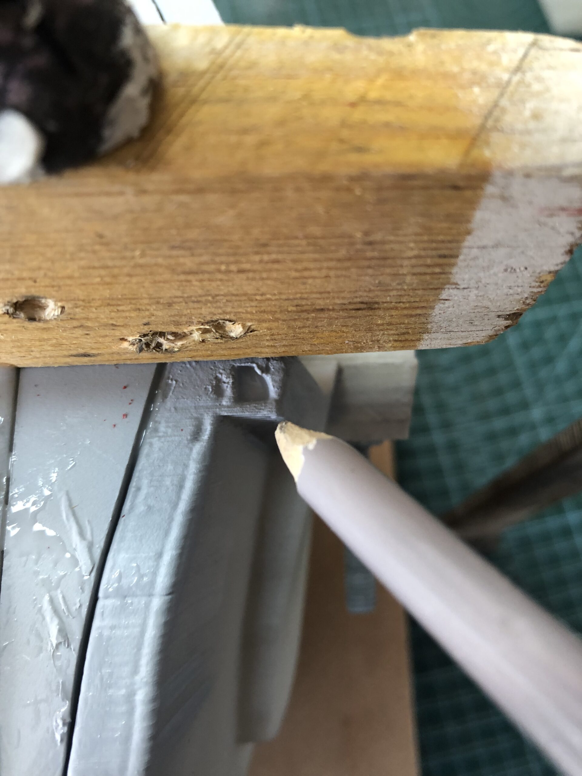
You can use clamps and a piece of wood to keep the three parts aligned. You can also add two bolts on the edges the middle inner mold. At this point it is important to seal the mold, otherwise the silicone will leak. You can use hot glue gun or kinder doe to make the seal. Do not use hot glue or kinder doe on the top edges of the molds, as we need the air bubbles to be able to escape from these seams.
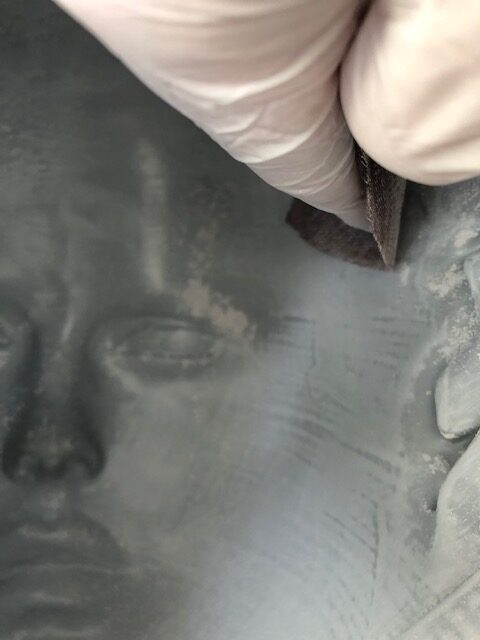
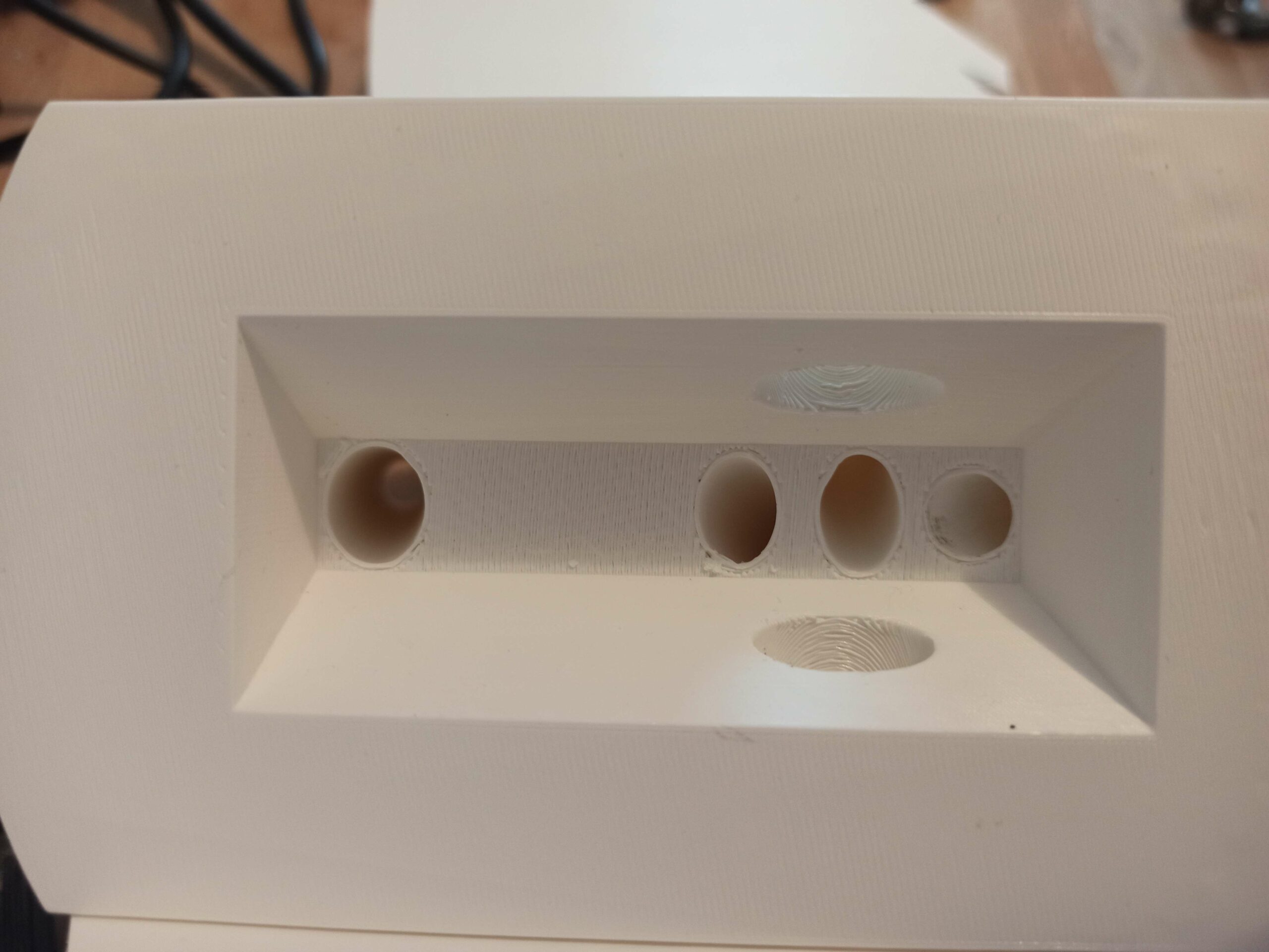
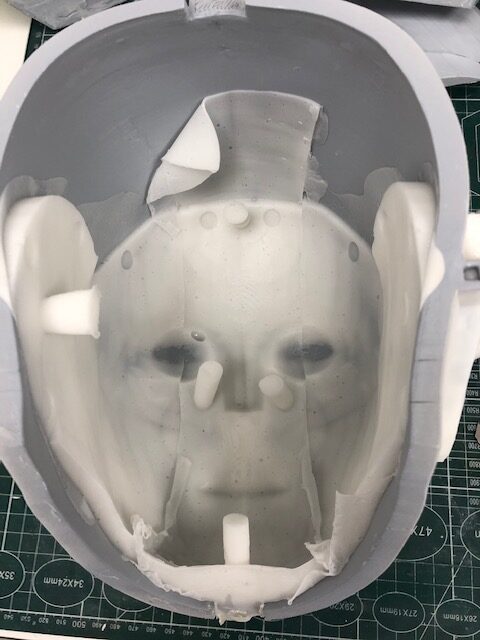
This is the recipient, where you are going to pour the silicone. Any gaps in your prints and the silicone will go in there. You can see on this picture, the print is very clean but there is very tiny gaps around the holes. The silicone will infiltrate through these if you haven’t sealed them all.
Prepare your silicone mix according to your reseller specifications. I recommend the Smooth-On Ecoflex 00-10 silicone because it is a super soft silicone which also has a low viscosity, this is good for what we need. You have a 30 minutes pot life to mix and pour the silicone. When pouring into the mold recipient, keep pouring all the time. And keep your silicone all the way to the top of the recipient like in the below picture. Otherwise bubbles might form in the tubes and would get drained down into the skin.
When the silicone reaches the little ear vents, it means it’s full. But keep making sure the recipient stays full to the top. The silicone is infiltrating the gaps between the inner molds, so level of the silicone might still go down.
Let the silicone cure overnight. Then you can remove the hot glue sealant with alcohol, it should come off rather easily.
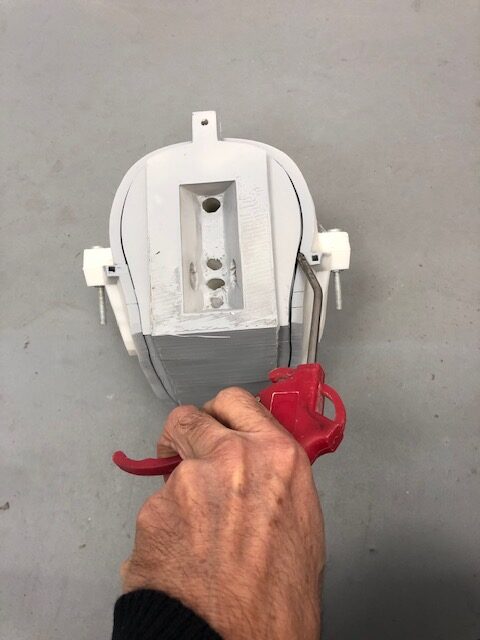
You can pull out the silicone from the recipient and cut with scissors the silicone in the tubes. To release the inner molds and silicone, I used my air compressor, it really helps to separate the silicone from the molds. You can blow the air through the ear vents, in the recipient holes and all sides where you estimate it might help to separate the skin from the molds. In case it really, really, really doesn’t come out, you can remove the 5 bolts and separate the two outer molds.
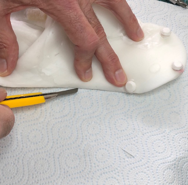
Once the skin is removed, you can use some baby powder (talc) on the skin surface to remove the tackiness. Cut all exceeding seams of silicone with a exacto knife or scissors. Scissors tend to make dents and might not do clean edges. It is best to lay the skin on a paper towel and cut precisely with the exacto knife.
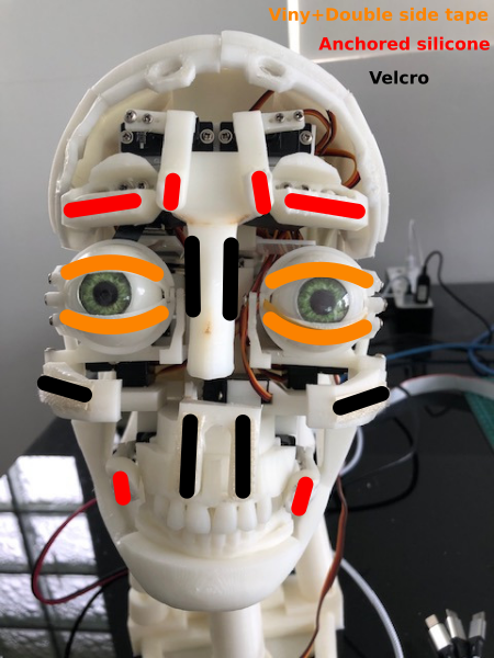
Using some small amounts of silicone or SilPoxy, we are going to fix the skin to the moving parts. We are going to start with the eyelids which require a special method using double side tape and stretchy vinyl. The nose, cheek bones and upperLip can be attached with some Velcro strips glued to the skin and to the printed parts. The rest of the moving parts are somehow anchored with silicone filled in the small cavities and glued to the skin. These method will allows us to remove the skin if necessary and to re-attach it again without having to glue again.
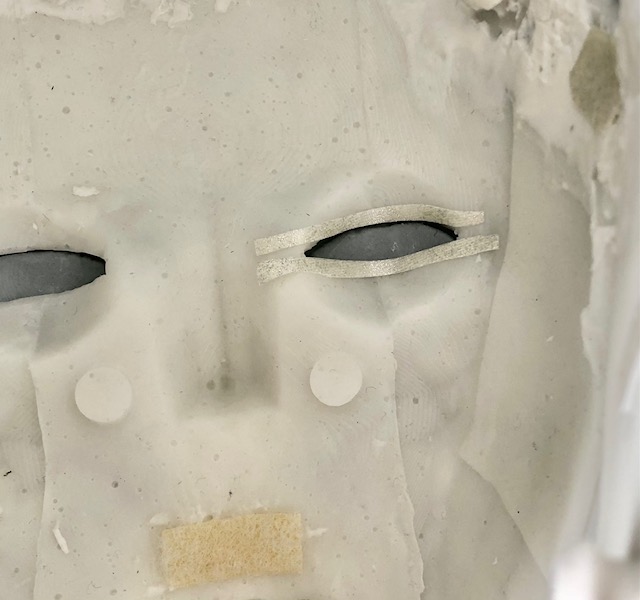
Apply and align by the edge of the eyelids small strips of double side tape. Make sure it glues really well. For a definitive fix, use Sil-Poxy or Dow Corning 732 glue.
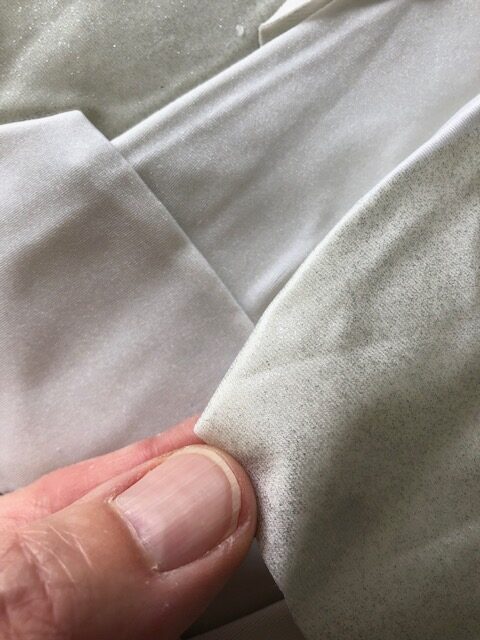
I used vinyl that has a clothe side and the other side is kind of plastic. When gluing the vinyl strips avoid putting silicone on the plastic side. If the vinyl doesn’t glue well to the double side tape, there is probably some silicone residue which should be clean up with a bit of acetone or some silicone remover.
Glue to the inside of the skin with SilPoxy or Dow Corning 732, along the edge of the eyelids, small strips of vinyl (glue the clothe side of the vinyl). Make sure it is well aligned. Do not make large strips because we want to keep the skin very stretchy. You can also see the Velcro strip glued with Silpoxy (or Dow Corning 732) for the upperLip.
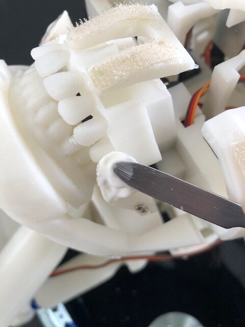
Applying the silicone in the small cavities to create anchors.
Here you can see, I used Velcro strips, which doesn’t work well when the moving part are rotating, such as the eyeBrows, cheekPuller, forHeads. It also adds a 2mm thickness, which can change the face structure, this is the reason I don’t use it every where.
Now we apply some SilPoxy ( or Dow Corning 732) on all the anchors and we mount the skin in place, making sure all parts are nicely aligned. Let the silicone cure before trying to move some servos.
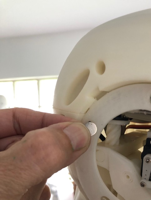
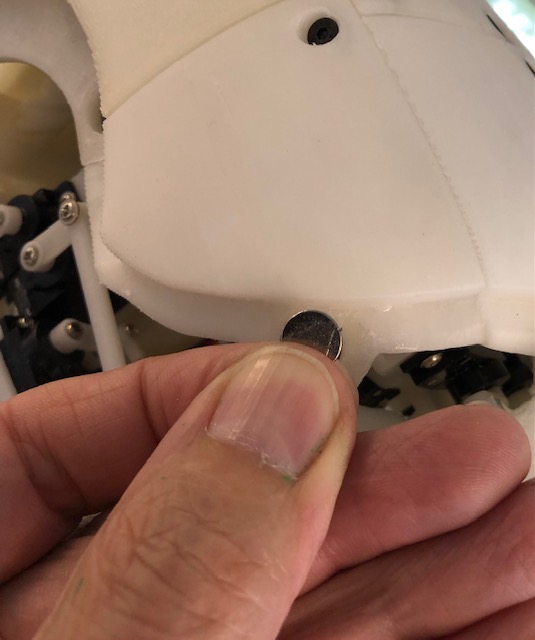
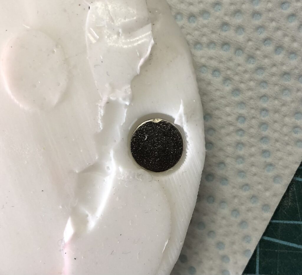
Glue the magnets with epoxy (two components glue) in the printed cavities of your printed head structure. Make sure to have the same polarity for all magnets in the printed parts.
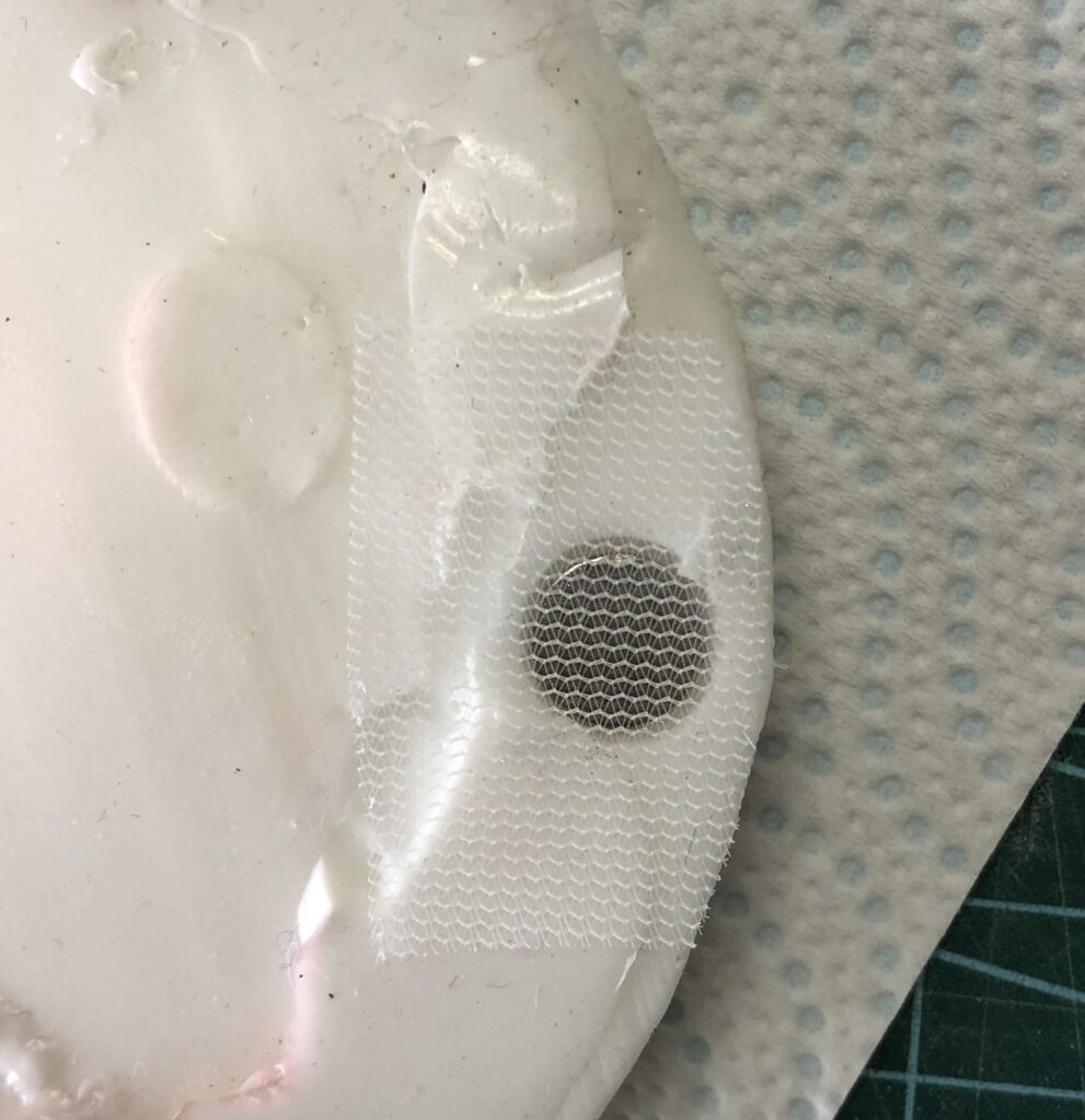
 Then glue with a thin clothe and Silpoxy ( or Dow Corning 732) the other magnets in the cavities of the silicone skin. Make sure the polarity of the magnets set in the skin will match the polarity magnets in the printed parts.
At this stage you can start testing the facial expressions in Myrobotlab and see how fun this is on the robot.
Start the adafruit 16 channel (pca9685) into InMoov UI under the controllers section.
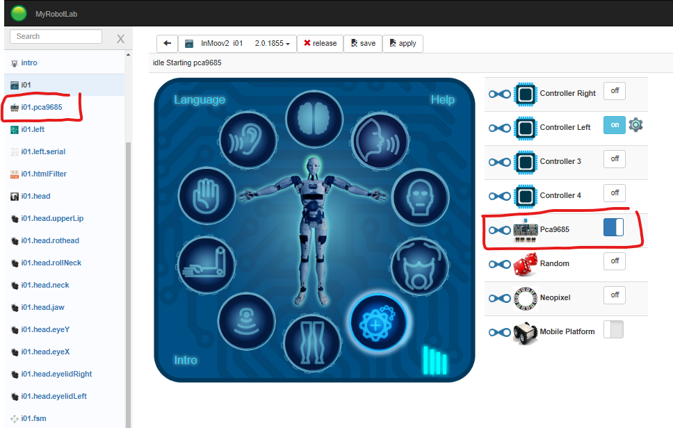
if your i01.left controller is already started, the pca9685 auto attach to the controller.
To get the i2Head UI, click on the bottom button.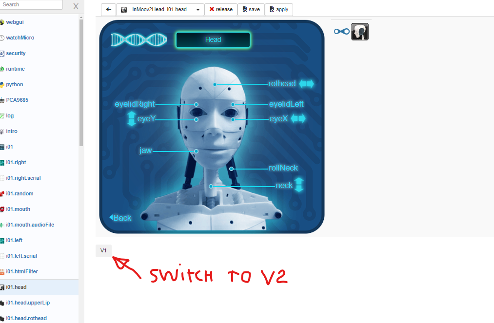
Then you need to start each head servo and select the pca9685 and define the proper pin in the scroll down.
Once that is done, you need to edit the limits and modify the output limits according to the maximum range of your servo.
Here are the voice commands to test the basic expressions:
- NEUTRAL
- ANGRY
- WINK
- DISGUST
- FEAR
- HAPPY
- SMILE
- SAD
- SIGH
- SORRY
- SUSPICIOUS
- THINKING
- UNAMUSED
Because many gestures were created for the original head, you will want to still be able to use them with the i2Head. For that reason it is mandatory to synchronize some old servo names with the new servo names.
As an example the eyes were called eyeX and eyeY which used only two servos, now we have four servos for the eyes, with respective names, eyeLeftLR, eyeRightLR, eyeLeftUD, eyeRightUD.
To synchronize the servos you can execute this script in the python tab of Myrobotlab and save your configuration.