Download STL files from the Gallery: i2RightHand i2LeftHand.
Before printing all the parts, you should print the CALIBRATOR, to check if your parts will fit together. If you have a very hard time putting those parts together, adjusting the horizontal expansion setting of your slicer software can solve that, this setting can vary depending of your slicer and printer but users report to set it at -0.15 is a great place to start.
Here is the list of parts and the number of prints needed for 1 right hand:
- 1x i2_CoverFingerV3
- 1x i2_FingersMoldX5V3
- 1x i2_FingersTipX5V2
- 1x i2_FingersX5V1
- 1x i2_HandCoverV1
- 1x i2_PalmCoverV2
- 1x i2_PulleyX5V1
- 1x i2_WristGearV1
- 1x i2_WristLargeV2
Print WristLarge, FingersMold, Fingers, WristGear, Pulley, resolution 0.25 maximum with an infill of 30%, wall thickness 2mm, no support, no raft.
Print CoverFinger, FingersTip, HandCover, PalmCover, resolution 0.25 maximum with an infill of 30%, wall thickness 2mm, support required, raft if your printer requires it.
BOM:
- 25x countersunk head screws M3 x 16mm
- 5x countersunk head screws M3 x 4mm
- 1x countersunk head screws M3 x 12mm
- 5x flat head screws M1.5 x 4mm
- 5x expansion springs 3/16″x1-3/4 or 4.8mm x 44.5mm
- 6x servo JX-6225MG 300 degree
- 1x ribbon 16 wires 3 meters
- 1x braided fishing line 0.8mm 200LB, 3 meters
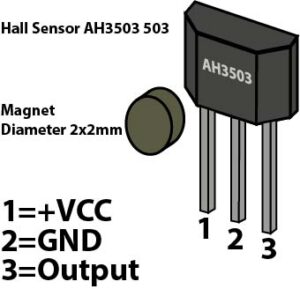
- 5x hall sensor AH3503
- 5x disc Magnet diameter 2.5mmx1mm
- 1x teflon pipes ID1.5MM X OD2.5MM, 3 meters
Step1
Glue the wrist servo support to RobCableFront
Mount the servo motor with 4 screws
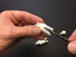
Redrill holes if necessary with a M3 drill bit
Redrill holes to allow the M3 PTFE tubes to run through them
Redrill hole with a M3 drill bit
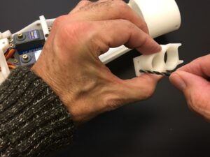
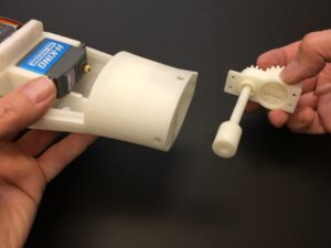
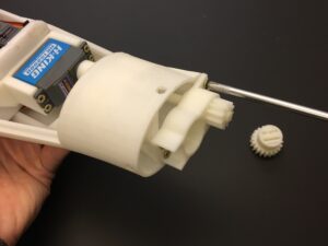
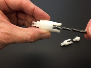
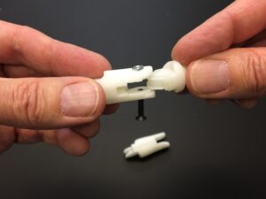
Glue together the two shaft printed parts
Check to make sure the shaft fits properly in the two printed gears
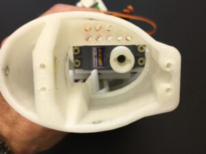
Mount RobCableFront and the servo support to the servo bed
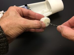
This view is to show you the assembly of WristGear and how those parts go together
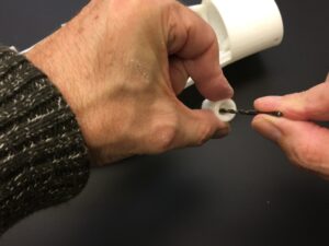
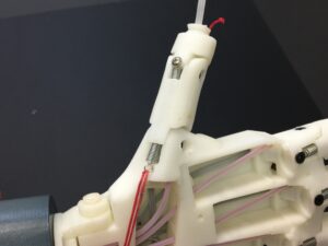
Set your servo approximately at 90 degrees(HK15298B) or 150 degrees(JX-6225MG) . (Midway of it’s total range). You can use this script to do that. Mount with a 3mm screw the end tip of the assembly to the servo shaft
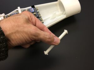
Screw the assembly to the wrist with 4 screws
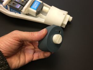
Assemble the main gear as shown
Note the head of the small gear has to be fitting in the reserved hole of RotaWrist2
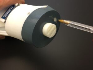
With a M3 tap, align the main gear and RotaWrist3, and add a M3 x 12 mm screw to fix them together
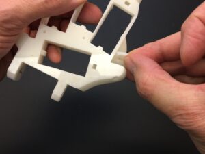
Remove that piece of printed pre-support, You don’t need that anymore
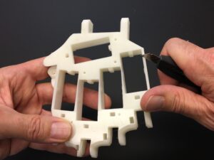
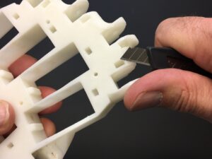
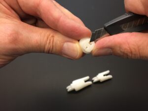
With a sharp blade, clean up the edges if necessary
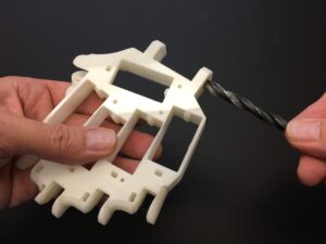
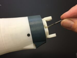
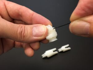
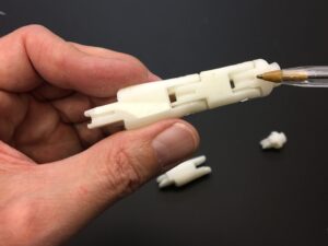
Redrill with a M8 drill bit WristLarge
With a M3 tap, prepare the holes for some M3 x 16 mm screws where the hand covers are going to be fixed
With a M3 tap, prepare the holes for some M3 x 16 mm screws where the springs are going to be attached
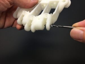
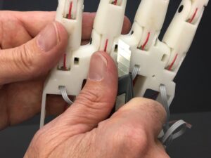
With a M3 drill bit, clear up all the holes which will attach each finger
With a M3 drill bit, clear up all the holes of each 3 sections of all fingers
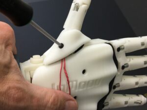
With a sharp blade, clear up the exit for the hall sensor
With a M1.5 drill bit, clear up the hole where the end of the spring will be attached
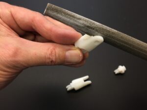
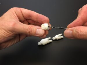
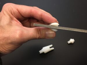
With a fill, make sure the three sections of each finger fits and moves really smoothly. This is super important to have good working fingers
With a M5.5 drill bit, clear up this finger section to allow the spring to run through properly
With a M5.5 drill bit, clear up this finger section to allow the spring to run through properly
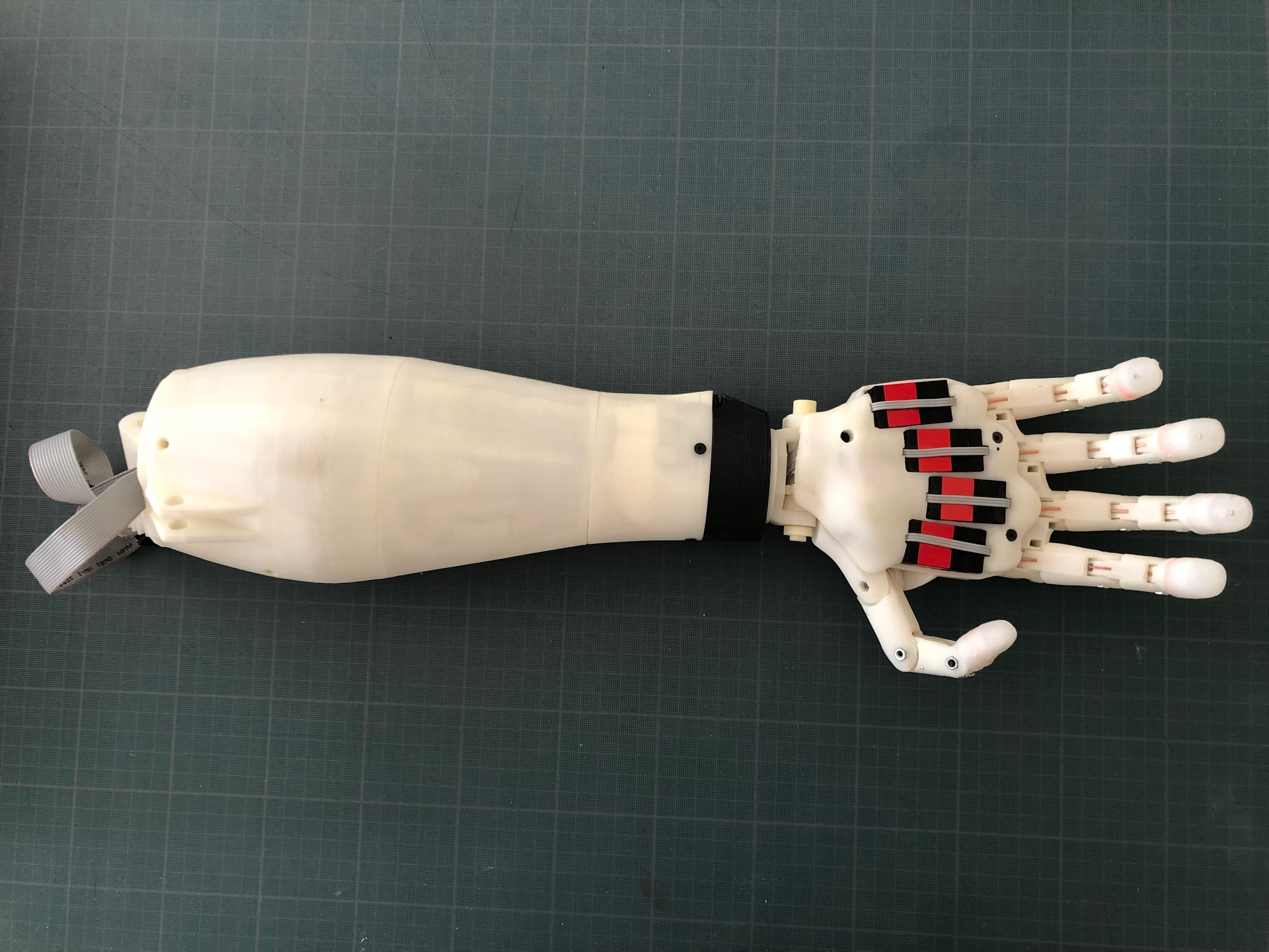
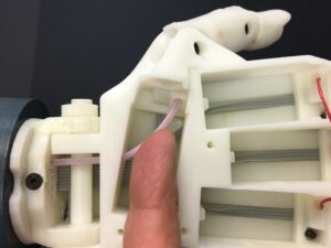
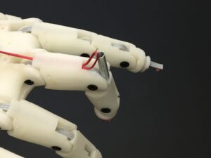
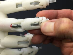
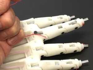
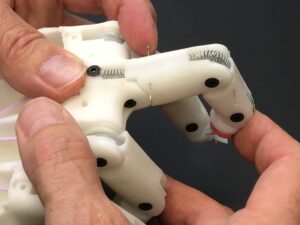
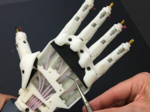
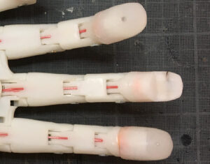
This is to show you how the spring and the three sensor wires will be mounted in each finger section
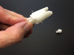
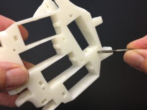
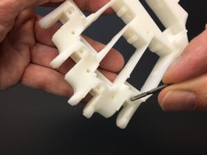
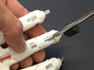
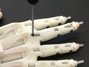
Make sure a needle can slide through each finger section as shown, otherwise clear up the holes
Add and mount finger sections together using M3 x 16 mm screws and bolts
Make sure the entrances for the braided fishing line are cleared up as well
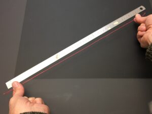
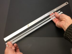
Prepare 5 length of 50cm of braided fishing line (0.8mm 200LB) You can find that product if you type in google search with these key words: braided fishing line 0.8mm 200LB
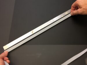
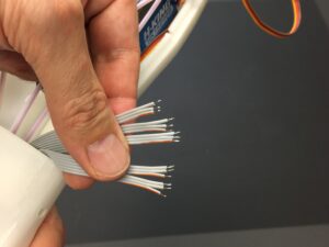
Prepare a length of ribbon cable of 40cm. You can google search with these keywords: ribbon cable 16 pin (make sure to get the most flexible and thin as possible)
Separate the ribbon to have a length of 40cm with 6 wires and another one with 10 wires
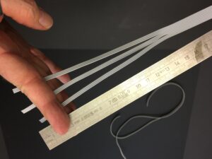
Remove completely 1 wire from the 10 wires section. Separate the 9 wires section to have three sections of 3 wires on a 15cm length
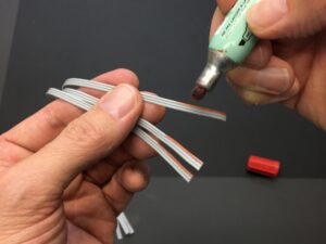
With a red marker, color one wire on each section. We will assume these are the positive (+) wires
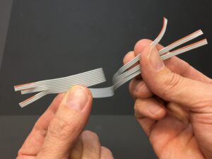
Do these coloring on both end of the ribbons, this will be very useful to avoid mixing wires when we will do the final soldering.
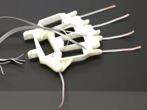
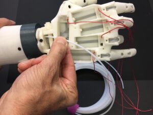
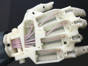
Run through WristLarge each 5 ribbon sections
Run the ribbons through each fingers, look out not to mount the fingers upside down. Also note that each finger are similar, only the thumb differs with it’s shape.
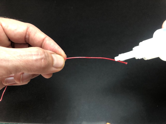
Now run the braided fishing lines through each fingers. To make the fishing line stiff on the end tip, it is useful to add some superglue.
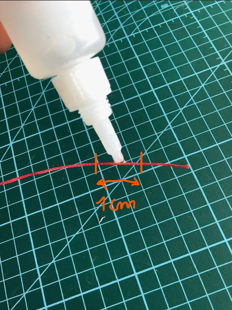
Add superglue on a 1 cm length of the braided fishing line.
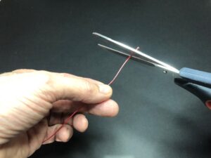
Wait until it is completely dry and cut the glued section in the middle, this will ensure a strong and thin tip.
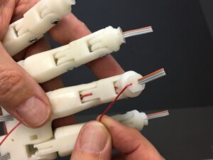
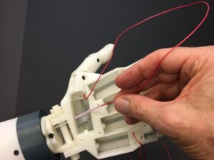
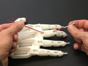
By pulling the fishing line as shown into the V groove of the finger tip, you can get attached
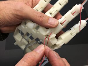
Now run the other tip of the fishing line into the hole of WristLarge
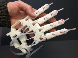
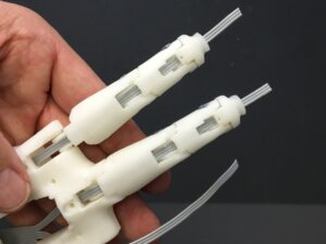
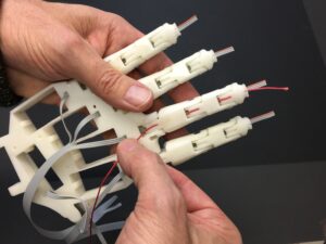
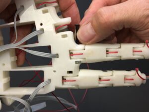
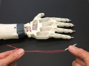
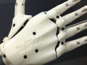
This is to show you how it should look like. On my picture I haven’t done the thumb yet, but you can do it. All five fingers can be done at the same time.
If you haven’t done it, clear up the 3mm bolt casings for the next step
It’s now time to add the M3 x 16 mm screws and their respective bolts to assemble the fingers to WristLarge. Start with Majeure finger, then Index finger, Ring finger, Pinky and finish with Thumb
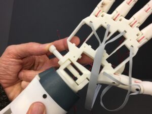
Mount WristLarge to RotaWrist3 with the appropriate M8 printed bolt
Set the mini clamp on the groove of the printed bolt
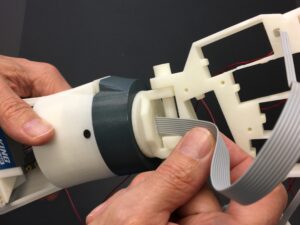
Run through the main gear the largest ribbon
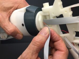
Then run through the main gear the second ribbon
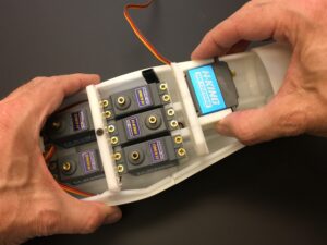
Place and screw the palm cover with 3 screws of M3 x 16 mm
When screwing the palm cover, make sure to set neatly your ribbons in the grooves and really avoid pinching them
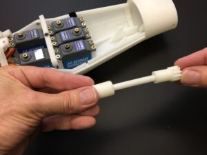
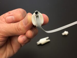
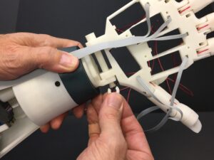
Now run the M2.5 PTFE tubes through the main gear Teflon pipes ID1.5MM X OD2.5MM The PTFE tubes are with the following lengths: Thumb 335mm Index 300mm Middle 300mm Ring 300mm Pinky 360mm
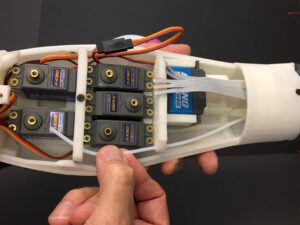
Run the tube through the the servo bed holes. Approach the tube to the servo shaft at about 1.5cm
Run the fishing line through the tube
And place the end of the tube into the reserved hole until it cannot go further
Repeat the operation for each finger
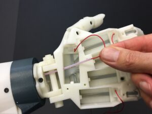
Run through one side of the spring a piece of fishing line. The total length of the fishing line should be about 30cm
Run the fishing line through the spring hole of the main finger section
Run the spring through the second finger section
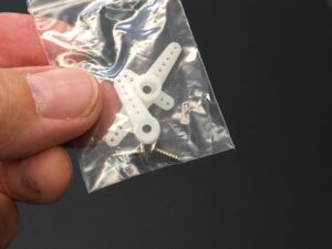
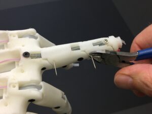
Get 5 small screws, I used some from the servos that are mounted in the eye mechanism, the diameter of these screws is about 2mm
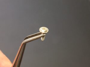
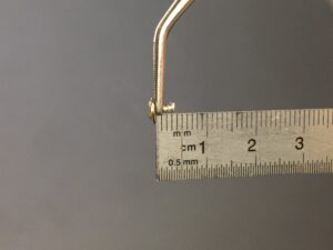
Cut with pliers the screw to be a maximum total length of 4mm
Hold the spring in place
And mount that small screw to set the spring in place. Make sure the screw is not piercing the three ribbon wires
Get or cut five screws of 3mm with a maximum length of 4mm
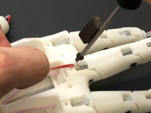
Pull the fishing line to get the spring tip to be in place and mount the screw. Note, I use a black magnet on my screw driver to ease the action of setting the screw
Before tightening the screw, withdraw the fishing line
Finish tightening. Make sure you are not piercing the three ribbon wires
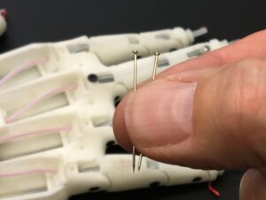
Get two needles
Fold the last section of the finger at maximum and run the first needle through the finger and spring until it comes out on the other side.
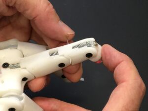
Fold the second section of the finger and run the second needle through the finger and the spring until it goes through. This allows to set adapted tension on each finger section
Cut the needles with a small pliers
Put a drop of super glue to ensure the needle won’t come out anymore
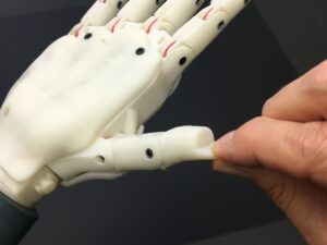
Time to do the same with the thumb, there is only two finger sections, so the spring is less in tension and doesn’t require needles
The other difference with the thumb, is that we set the screw into the cover which then holds the spring in place. Make sure not to pierce the wires. Although my picture shows the HandCover being already attached, don’t attach it yet, you still need to access the inside
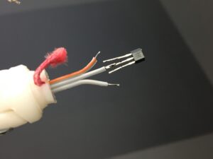
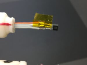
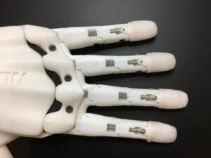
Let’s solder the hall sensor to the wires. Start soldering the middle wire. Note the position of the sensor on my picture, because one side is positive and the other is negative. HALL sensors AH3503
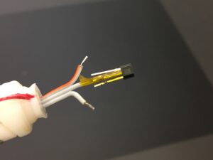
Protect your solder with a small piece of tape. I used Kapton tape. This is delicate to do.
Solder the second and third wire and wrap them up with tape
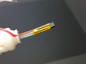
When wrapping the tape, you shouldn’t make it thicker than the ribbon itself, otherwise you will have trouble pushing it down for the next step.
Push it back into the finger tip carefully
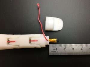
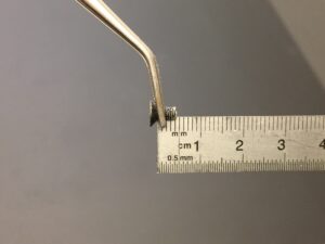
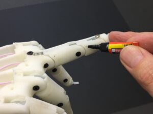
This is the length of what should be sticking out of the finger tip
You can pull the wires in the palm to help yourself to push the hall sensor back into the tip
Wrap the fishing line around the groove, and carefully screw the end of the finger over the sensor.
Note the end of the finger is printed with a small threading to allow it to be screwed clockwise to the finger tip. Don’t force, otherwise the threading will be damaged.

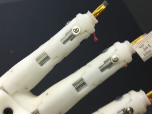
Finish the operation for each finger.
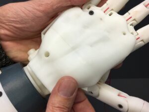
You can mount the finger cover with some 16x3mm screws. Although my picture shows the HandCover being already attached, but don’t attach it yet, you still need to access the inside
Time to solder each wires to the sensor mini board of the NervoBoard. Thumb goes on « 0 », Index on « 1 », Majeure on « 2 », RingFinger on « 3 », Pinky on « 4 »
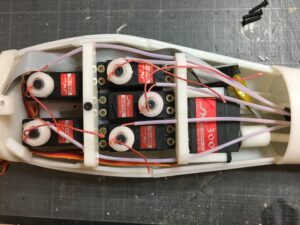
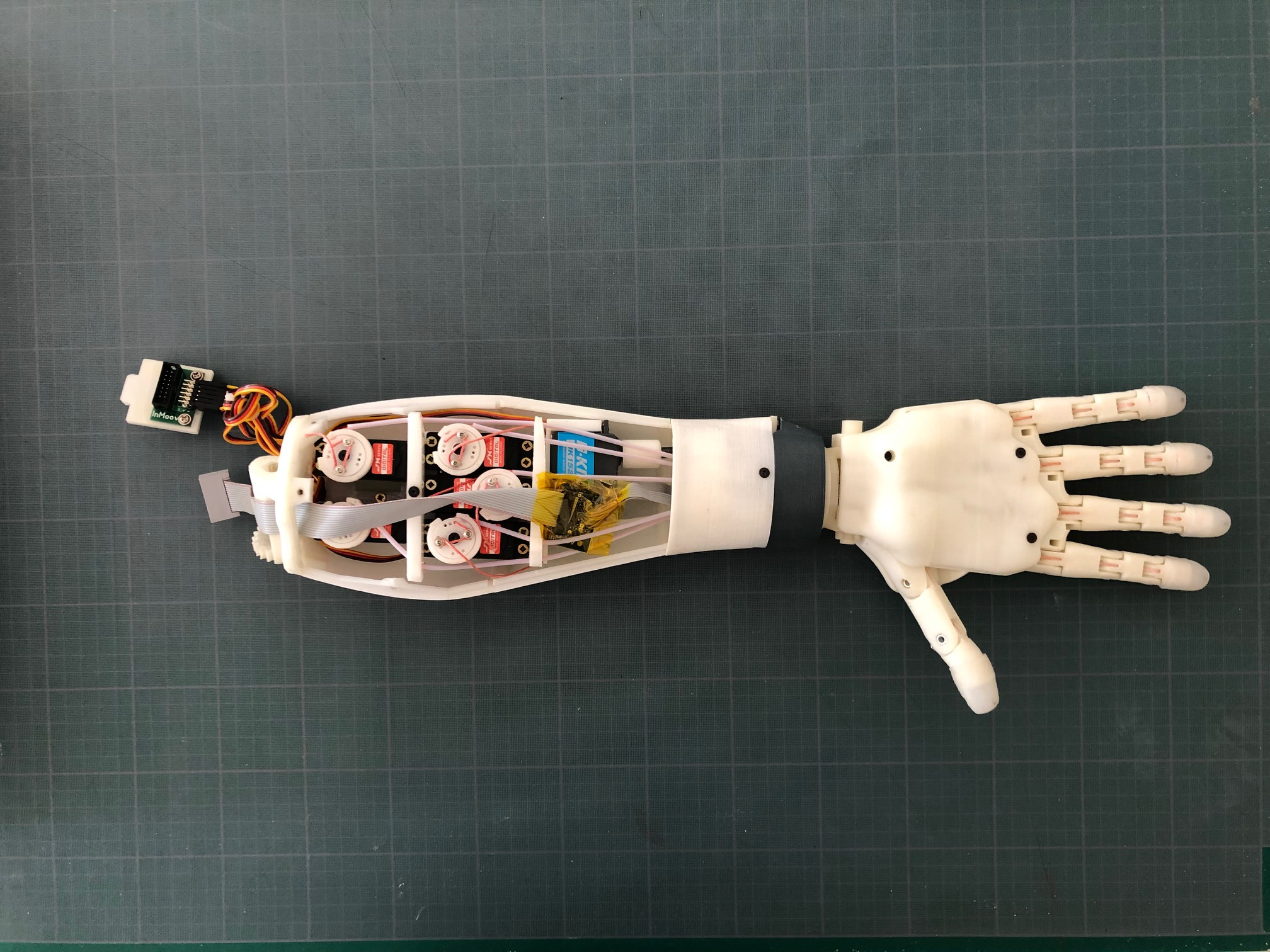
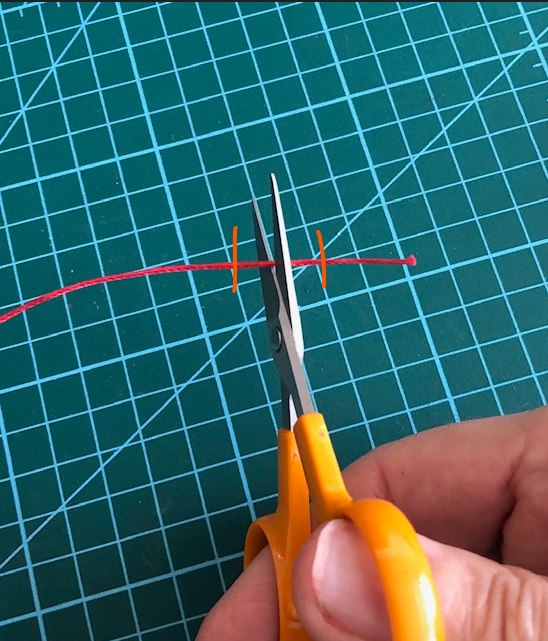
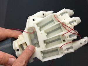
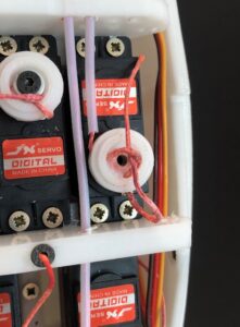
Here you can see where I have set my mini analog board. You can also see on the pulleys, how the screws with a small washer are holding the fishing line in place with a single knot. To do that, you need to add some glue on your fishing braided lines at the point you want to cut them.
To do that, you need to add some glue on your fishing braided lines at the point you want to cut them, let the contact glue cure. The glue makes it easier to get a clean cut.
Then, use sharp scissors to cut where you have put glue.
Run your fishing line the way I did it in this picture, it should make a big knot.
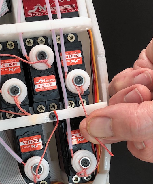
Tight the knot, set your screw and washer on the knot, and maintain the knot pulled while finishing tightening the screw. .
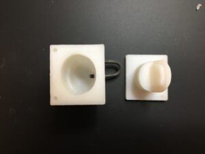
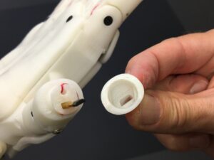
In the molds, there is a hole to insert a section of 2mm diameter, which will allow to create a reset in the molded silicone for the magnet to take place. Disc Magnet diameter 2.5mmx1mm
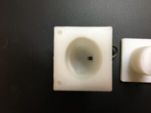
Make it go through of 2mm. I used two component clear RTV silicone Ecoflex™ 00-10
Glue with silicone kit the molded parts on each finger tip
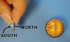
Determine the South pole of your magnet with a compass.
Insert the magnet with the South pole facing the hall sensor into the reset of the silicone molded tip. Use wooden toothpick to do that, because any metal tool will stick to the magnet. This is delicate to do, and should be well done to get proper results. Secure the magnet position with a drop of silicone kit, and wait for it to dry. Test your sensors with this page https://inmoov.fr/test-your-finger-sensor/