Building the bicep of InMoov

I have tried to make this as simple as I could, and I hope you will find answers to your questions here. Once you have printed the parts you can start the job. On these pictures I was assembling the left arm so take that in consideration if you are building the right arm.

Download STL from the Gallery

Before printing all the parts you should print the CALIBRATOR, to check if your parts will fit together. If you have a very hard time putting those parts together, adjusting the horizontal expansion setting of your slicer software can solve that, this setting can vary depending of your slicer and printer but users report to set it at -0.15 is a great place to start.

An infill of 30%, wall thickness 2.5mm, best with no raft, no support, use a brim for big parts to avoid warping.

Here is the list of parts and the number of prints needed for 1 right bicep:

  • 1x GearHolder
  • 2x HighArmSide
  • 1x Pistonanticlock
  • 1x Pistonbaseanti
  • 1x RotGear
  • 1x RotMit
  • 2x PivPotentio (round or square)
  • 1x RotTit
  • 1x RotWorm
  • 1x Rotcenter
  • 1x armtopcover1
  • 1x armtopcover2
  • 1x armtopcover3
  • 1x elbowshaftgear
  • 1x gearpotentio
  • 2x lowarmside
  • 2x reinforcer
  • 1x servobase
  • 1x servoholder
  • 1x spacer

Here is the list of parts and the number of prints needed for 1 left bicep:

  • 1x GearHolder
  • 2x HighArmSide
  • 1x Pistonanticlock
  • 1x Pistonbaseanti
  • 1x RotGear
  • 1x RotMit
  • 2x PivPotentio (round or square)
  • 1x LeftRotTit
  • 1x RotWorm
  • 1x LeftRotcenter
  • 1x armtopcover1
  • 1x armtopcover2
  • 1x armtopcover3
  • 1x elbowshaftgear
  • 1x gearpotentio
  • 2x lowarmside
  • 2x reinforcer
  • 1x servobase
  • 1x servoholder
  • 1x spacer


STEP1:

What we want to do in this first tuto is to extract the potentiometer of the 2 servos and adding by welding, extra cable length:

We will start by opening the Hitec HS-805BB servo by unscrewing all the screws at the bottom. It comes apart in three sections. Make sure to work in a clean place, you don’t want to lose anything and spoil the grease it contains. Once the top is removed, note or take a picture of each gears placement, check well there are two looking almost alike (shown on picture).

Remove the bearing and it’s rings(note the order). It can be a little hard to remove it, I used a small screw driver placed under the bearing.

Now we want to remove the pcb card and it’s motor, on some servos it just came easy, but there is a bit of glue around the motor, so you can push the motor down by pressing the little metal gear placed at the tip of my screw driver.

Here is another solution posted by an InMoov builder, if you can’t open up your servo the way I did it, of course if you have a solder pump, it will be even easier:

Or this video:

Or you can also watch these videos posted by a InMoov builder:

Here is another set of videos, in which the technique involved is to remove the solder on the three motor connections, leaving the motor in place instead of romoving it:

A PDF for to extract the potentiometer on a JX-PDI2060MG servo:


Aaah, it came out, unscrew the potentiometer, for to release it out see next picture.

help yourself again with your small screwdriver placed under the big gear.

Remove the plastic washer(we won’t need it anymore, but keep it you never know…)

This is a bit tough, cut the “stopper” with a knife or pliers, BUT DON’T DAMAGE THE GEAR.

Remount all the gears back in there original place. Arrange with your knife a bigger opening for the extra length cables. When unwelding the cables from the board and the potentiometer note the colors. (I didn’t with my first servo, answered the phone for ten minutes and when I went back for welding I couldn’ remember the colors… Caused to damage the servo permanently, 30euros in the trash, Aaargh)

Before welding the potentiometer of the low part of bicep, run your cables in the gap of “servoholderV1”.

Important note: do not de-solder the potentiometer wires from the PCB of the servo, just cut them and solder the extra length you need. Some builders have reported having none working servos after soldering directly on the PCB controller. Some components might be very delicate to temperature.

For the low part servo of the bicep, your cables should be welded in the same color order as when you opened the servo. Your cables should be about 25/30 cm long. Now we are set for to assemble the parts.

Here is another solution (by Wayne Kinne) if you can’t open up your servo the way I did it, of course if you have a solder pomp, it will be even easier:

You can also watch these videos posted by a InMoov builder (byKaibab):

Here is another set of videos (by Yann Huguenin), in which the technique involved is to remove the solder on the three motor connections, leaving the motor in place instead of romoving it:

STEP2:

This picture is to show you what is the angle position of “rotgearV1” compared to “rotmitV1”. Check the little rectangle hole.

So keeping the same rotation angle, mount “rotmitV1” to “rotgearV1”. (Don’t refer to this picture for the angle, parts you’ve downloaded aren’t the same anymore)

I used clamps to make sure there wouldn’t backlash between all three parts during screwing them. Make sure your screws don’t come out behind, or recut them. (Don’t refer to this picture for the angle, parts you’ve downloaded aren’t the same anymore)

Attach one servo to “rotcenterV1”. For to do so: mount but don’t tight fit the white actuator wheel.

Once the servo is attached, you can tight the screw.

Mount “rotwormV4” to the actuator with 4 little screws, make sure they don’t come out behind the actuator, otherwise you have to cut them. Mount “rotgearV2” to “rotcenterV2”, it should turn easily but with no backlash. I made it operate a few turns by plugging the servo on the Arduino. Then I cleaned up the dust created by the parts. Before closing the case with “rotTitV1”, use a good amount of grease, every where on the gears.

If you are building the left ROTATE arm, your cables should be welded in the same color order as when you opened the servo.

If you are building the right ROTATE  arm, your cables should be welded in the opposite color order as when you opened the servo.

Mount the potentiometer to “rotpotentioV2” but make sure to place the little metal plate from the potentiometer in the gap designed in “rotpotentioV2”. Use some little spare screws from your small servos.

PS: “rotmitV2 was not supposed to be standing on the left on three above pictures, since you already have mounted it…

Ease “pistonanticlockV1” in to “pistonbaseV1”. I have reinforced “pistonanticlockV1” on the inside with a metal rod. But you can use it like this, it should hold. I broke a few of them during my tests, and was glad they could break instead of something else.

Assemble “higharmV1” to “rotmitV1″”, use pliers , with ABS it just fit perfectly, I felt like playing with Lego’s. Make sure you have the same position then on the picture.

Add “pistonbaseV1” and “spacerV1”. Attach the potentiometer, again make sure to place the little metal plate from the potentiometer in the gap designed.

Assemble the rest of “higharmV1” and “lowarmV1”. Later, after your tests, you will have to glue those parts.

Attach the servo in the “servoholderV1”.

Run the cables as shown.

Tuck down the cable along the frame as shown on this picture, I used aluminium tape, this will avoid pinching the cable during actuations.  Do the same on the other side with the potentiometer wires.
DSC05166bis

Attach the “servobaseV1”, and “pistonanticlockV1” to the actuator.

Turn in “pistonanticlockV1” in to “pistonbaseV1”. Adding grease is a good idea.

So I assume here you already have glued “elbowshaftgearV1” to “robcap3V1”. So you also have attached the forarm to the bicep. Good.

Here comes the part the most difficult for me to explain. Now lean down “servobase” and attache it to the forarm.

You should KEEP a gap at it’s base, this is going to be your 0° degree position. Fix or mark the whole arm in this position, it is important not to lose it during the next steps.

servogun

Unmount the servo gun. Plug your servo to the Arduino board, and run a sketch to get the 0° position of your servo, it will rotate continuously. Now turn by hand the potentiometer until the servo stops turning. This is your 0° degree position.

Mount the “potentiogearV1” on the potentiometer, making sure the arm and the potentiometer don’t move.

Clip in the “gearholderV1”. There should not be backlash between the two gears. Keep the servo gun unmounted and make a test with your Arduino like previously to 0°degree. You can move the arm slowly by hand to closed position and open position to check everything is okay. Remount the servo gun.

Big moment now. Rerun the test to 0°degree. The arm should open keeping the gap previously seen at the base. If not it will break the “pistonanticlockV1”.

Make another test from 0°degree to 60°degree. Check the space left between “pistonanticlockV1” and “pistonbaseV1”. My arm can go up to 90°, but be carefull that all depends on the gap you have set. So try 10° by 10°degrees. Remember when writing your sketchs to never go further then the best result you got.
Now you can make a test with the servo attached to “rotcenterV1” going to 90°, that will be the “rest” position of the arm when it will be attached to the coming shoulder.

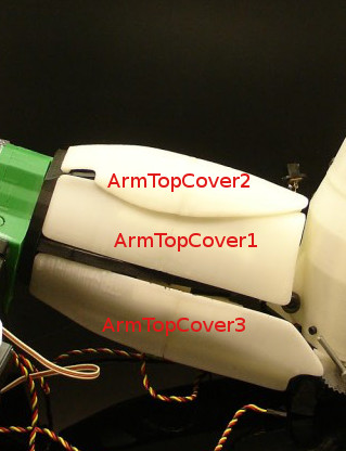
Add the covers on the bicep to reinforce the structure.

There is no support to remove on these parts. But you need to cut the tiny connectors, between the parts, to separate them. A cutter blade works with ABS, you might need to use a knife with teeth, if printed in PLA.
Bicep3

The covers are glued together to match the bicep like on this picture:

Bicep2

Normally you should be all set. Hope this helped because it took me a lot of time to do this tuto 🙂

Comments 129

  1. Hello everyone,
    I wanted to share my expereince on editing a new servo motor Hitec HS-805BB.
    I use GoogleTranslate to translate my message, welcome corrections)
    I do not know if I got trouble, but it was impossible to remove the circuit and motor part, I stopped before breaking everything!
    To change this model I found a technique that involves removing solder pins 3 engine with a pump for welding (you can also use the copper braid)
    Indeed the circuit is only attached to the engine, it allows not to damage mechanics.
    After removing the potentiometer is welded donations again 3 pins
    Another trick to remove the rotation limitation on the final gear, I removed the upper part of the hood, leaving all the gears in place on the part of the middle, and then I cut with wire cutters vertically a little, then a little horizontally and then switch it continant has ended up breaking impeccable.
    Then simply with a cutter to finalize, to make a full turn to ensure that this does not crooked. Be careful not to leave any piece of plastic in the servo and close, easy!

  2. hi Gael,

    iam working on bicep and shoulder i removed the potentiometer from HS-805BB, but i am seeing in pictures that u are mounting a different (metal pot) potentiometer on rotomitv2. do we have to change the potentiometer to mount on rotomit v2

    can i know the specifications of that potentiometer please.

    thank you.

  3. Hi,

    I’d like to access the “Sketch Motion Biceps” link but when I clic on it, it sends me to an other page “http://www.creatic-agency.fr/clients/inmoov/Sketch-Motions-Bicep/” and it asks for a special admin authorization which I don’t think I can get.

    How should I manage to get the Arduinos sketches ?

    I need to control the servo with the potentiometer, I need a linear relation between the potentiometer’s and the servo’s angle.

    Thank you for your help 🙂

  4. I haven’t looked at this too closely but can someone explain to me why we are removing the potentiometer from the servo? I would feel much safer about adding an additional potentiometer and having the code compensate for what you are trying to achieve(I’m guessing it is just to have a status of where the arm is?)

    • The pot gives the angle position of the arm. A servo turns only 180 degrees, which is not enough to move fully the arm. setting the potentiometer on the elbow lets the servo rotate many turns, letting the arm to its full potential of movement.

  5. I have a question, so for the bicep I need 2 servos, one that will be hacked and the potentiometer made longer and it is attached to the side of the bicep part, and one servo untouched as is, that goes in the middle?

  6. Hello Gael,

    I have a question. Instead of HS 805BB Servo, I am planning to use HS 311 Servo. I know it has low specs, but still keeping in mind the cost factor, I planned to use HS 311. My doubt is whether it will work properly? And also, how will the servoholderV1.stl fit the new servo?

    Thanks in advance.

    • You can use the InMoov3minimal.Arm.py
      to test the servo in the arm. This script is for the latest versions of MRL.
      If you are using the version 1.0.107, use this InMoov2minimal.Arm.py

      A good way to test, is to have the potentiometer removed from it’s holder, and the servo set in its holder with the piston fixed but not engaged in the piston base. Turning the pot manually will let you see if the piston rotates in the correct direction. Once this is secure, you can mount the pot in its holder and check if its position is correct. This method can be applied to all the hacked servos.

      You can use the attach-detach button on the servo slider in MRL. Remember that the scripts you are using have default Min and Max setup for each servo. Which can be confusing if you don’t know about that. For to know the defaults mappings check the Hardware list.

  7. “Unmount the servo gun.”
    Hi Gael. I have just finished to assembles hands and forearms and started with biceps but I am at a loss regarding the statement “Unmount the servo gun.”.May be my knowledge of English is somewhat limited, but I cannot visualize a “gun” in a servo.Obviously it refers to something different than a pistol or a rifle,but ,in spite of all my efforts, I have not been able to identify it.I was afraid about the servo disassembling, but, on the contrary, it went like a breeze (by unsoldering the board, i.e.- and yes, I have a desoldering pump,very old but still efficient). On the contrary, I am now stuck with the biceps assembly. Could you kindly help? Thanks a lot.

    Andrea

    • Hello Andrea,
      I am glad it went smoothly with the disassembly of the servo. Indeed a despldering pump is a great tool for this kind of work.
      Regarding your question about the “servo gun”… Remember when you were a kid, you use to look at clouds and you would see faces, horses, dragons and maybe even a gun or a rifle, well it was the same for me during creating the bicep assembly. For some reason I saw a gun in this picture:

      I hope this helps
      🙂

  8. Hello Gael,
    I had given a thought of the supposed meaning of “servo gun”,because it looks like a gun for sure, but better …….make it sure!
    Sorry to thank you only now, but I am presently not busy with the project because servos are not available neither in Italy nor in UK (at a decent price i.e.).They will arrive any time in October, therefore I keep on waiting before going on.I have had some problem in adapting gears and worms,because they do not fit immediately.Having a lathe, I have been able to adjust the diameter when necessary, but some other parts needed a pretty painful work of Dremel and file.I guess this is the price one has to pay in making his own 3D parts,though my 3D printer is a Creator Flashforge Pro, which is not among the worst ones.Anyway, keep going with your extremely interesting project and, please, with your valuable online help.
    Andrea

  9. Hi Gael. I would like to suggest an easy improvement on the design. I have broken the servo pot because for some reason, the servo decided to go outside the pot’s mechanical motion range. To prevent this, could you fill in the gaps between the teeth of the gear so that if the electronics go bad for some reason, the worm would mechanically block on the gear and preventing excessive rotation that would break the pot. I rather see a printed worm shaft break than a hard to find 180 degree rotation range linear pot (all the ones I found have a 270 deg rotation range). This must be a wise decision as the tab we cut off on the large gear in the servo is there for that exact reason, to protect the pot.

    It’s just a suggestion to improov this nice design. 😉

    • Hello Ivan,
      I’m guessing you are not referring to the pot of the Bicep but the pot of Rotate and Shoulder(RotGear, PivGear)
      Indeed it is something I have already considered, although once the pot is correctly set and script configured, it never goes beyond it’s point.
      That being said, we are never safe enough! If I do have some time, I will see what I could do to add safety.
      Did you use my latest (RotGear, PivGear) V5 ? The pot holder could have a shaft to prevent excessive rotation.

      • dear Mr.Gael, I’m a 12 year old and I’m new to robotics, I decided to build InMoov myself after I found out about you, InMoov is a great robot, but I’m having trouble understanding how InMoov works and how to do the wiring, so could you please help me with building InMoov, any reply is more than welcome, you can contact me with my gmail: sahasnapege2008@gmail.com

        Thank You

  10. Yes I did… I have servos with a square pot and a blade as shaft. Out of nowhere, one of the shoulder servos decided to rotate out of control. By the time I understood what was going on and killed power, it was too late for the pot. I don’t understand exactly what is going on, I also have a second servo that started doing the same thing now but I stopped it on time. Not sure if it’s the arduino sending a bad duty cycle or the servo electronics going bad…. but the servos seem to kick into a continuous rotation mode, which isn’t normal and results in damage. Since the pot is square, it won’t turn if there is excess torque applied to the shaft. The shaft being flat, it wont slip either. From the outside all seems fine but an ohmmeter test shows the wiper no longer follows the shaft. If you have a suggested replacement part (digikey part # or something similar to get a round pot or a pot with round shaft that can slip and does full range in 180 deg), that would be nice.

  11. Sir,Thank you so much for this wonderful project that you have shared.We as a group of 2 people are building it following your footsteps for the application of cooking- as RoboChef. We are really grateful to you !

  12. Hello Gael,
    I had to re-install Windows on my PC and, in the process, I lost all the InMoov already downloaded files.In addition, I had to wait a long time for the delivery of servos and, losing contact with the project for such a long time, I got a little misguided as how to proceed properly. It looks like I have severe difficulties in making gears and worms work together. Eventually I have been able to have them engage properly, but with a lot of adjustment, which does not look right to me. I woul therefore kindly ask you:
    1.Are pivgears and rotgears identical or is there some difference between the two? I noticed that pivworms and rotworms are not identical , but, as both gears seem not to be presently available for dowload I cannot verify for gears . Could you please look into what happened with the dowload procedure’?
    2.Same for pivcenter and rotcenter(I understand that they are different as far as left and right is concerned, but what about the internal structure?
    3. Is it correct that space for servo arm (round) inside the center unit is not sufficient and some material has to be filed out?
    Last question, not related to this issue; what about leg project? Any new development?
    Thank you a lot for your patience.
    Merci encore et mes salutations amicales.
    Andrea

  13. Hi Gael,
    I just started to build my InMoov and I got to the Bicep part and I have a question, I can’t figure out, potentiomer mounted on “rotgear” should be set to 0 degree or to 90 degree before mounting? Or it doesn’t matter? I set up “rotgear” for the gap to be exactly like in your picture. But what about the potentiometer which goes to that gap? I’m asking because I think it matters and I can’t figure out.
    Anyway, Good Job with InMoov. I like it a lot.

  14. Hello Gael,

    Had a doubt about the potentiometer. i followed all the steps and took out the potentiometer from the HS-805BB motors. Now I write 0 degree to the motor and the motor keeps on rotating. But even though I rotate the potentiometer the motor DOES NOT STOP rotating.. Could you please help me out pointing what the problem could be ?

    Sinchan

    • If the pot is wired backwards turning the pot in the direction of movement will only increase the rate of movement. Verify it is not backwards by turning the pot the opposite direction of travel. If this works, you need to swap the pos and neg wires going to the pot. The signal wire stays the same.

  15. Hi Gael, we want to adapt your design as prosthetic for one of our recipient that lost both hand at the shoulder level. Our intention is to build a complete hand and torso assembly for him. However we will be resizing some of your measurements to fit the user.
    I will appreciate your technical input and that of any member of this forum in this tough but implementable journey that we are embarking on.
    Please reply me asap.
    Ayodele

  16. Hi Gael and makers!

    First of all, since this is my first post, congratulations to Gael for sharing this project and for his excelent job.
    My students are fascinated with InMoov so they decided to build one with my supervision.
    We bought the HS805BB and they have a square potentiometer.

    My question is, has anybody tried the derivative part “InMoov bicep lowArmSide for square potentiometer” by Ilkirius (https://www.thingiverse.com/thing:1464929)?
    Is the potentiometer with the right angle?

    Thank you all.

    • Seems you have one of these two issues:
      1-the wires polarity on your pot is inverted. De-solder, invert them to test.
      2-the servo you are using has a inversed motor polarity. (Some other servo than the HS805BB, like the HK15338 has that.)

  17. Hello Gael.
    For the biceps apart from the HS-805BB servo, you say that the servo PDI-HV2060MG also works. Is there any problem in using it or does it matter? To remove the potentiometer from the PDI-HV2060MG, is the same procedure as the HS-805BB?
    I have used the translator sorry for the failures that may have
    Thank you.

  18. Hi Gael, I’m Italian, I started printing a few days with a Zortrax M200 printer. I hope to be able to assemble the whole robot, it worries me it’s the electronic part ….

    I would like to meet Italians who are preparing for this project, my email jeep-chevy327 (ET) libero.it

    Thank you

    • Hello,
      You can check the world map and try to contact the Italians that have put their emails or make post to call out for Italians directly on the forum.
      We have a great Italian working on the project called ALESSANDRO DIDONNA, and also a Sicilian called LEONARDO TRIASSI. Both have been helping a lot for the project!

  19. A Gael question, I am not yet absolutely practical with arduino, I would like to know how I can “stifle” the moving parts of the bicipid with a continuous rotation of the servo. I have already changed the servo and removed the potentiometer. For the moment I do not want to connect the potentiometer, but I want the servo to turn freely continuously to make a break-in to the moving parts. What do you suggest me?

    Thank you
    Stefano

  20. Bonjour à tous!
    Gaël me corrigera si je dit une bêtise:
    Impression PLA : Après avoir bataillé des heures à poncer “pistonanticlock” pour qu’il puisse rentrer dans le bloc, j’eu enfin l’idée de modifier légèrement la taille d’impression de X et Y :
    X et Y à 0.97
    Z à 1
    résultat: un léger ponçage de 15min à la dremel et voila qu’il rentre sans forcer, sans jeu et sans soucis!
    Comme j’en suis pas au stade des essai de motorisation (j’attend mes ribbons câbles), je suis pas sur que cette légère modification de taille ai une incidence sur le fonctionnement.
    Gaël: si c’est bon, je pense que tu devrai ajouter cette info dans le tuto pour ceux qui peuvent rencontrer ce problème.

    Merci encore pour cette fabuleuse expérience!

    • Bonjour et merci pour votre ,
      C’est effectivement une technique qui a été mentionnées à plusieurs reprises sur le forum anglophone.
      Par contre de là, à la mettre dans le tutoriel, je ne suis pas sur que ce soit une bonne idée. (Je vais tout de même le suggérer , cela évitera que d’autre bataille des heures à poncer)
      Si les pièces ne s’assemblent pas correctement c’est un problème de calibration de la machine qui imprime légèrement surdimensionnée.
      Les réglages causant ce problème sont divers, extrusion trop importante, diamètre du filament non calibré, trop d’infill avec peu ou pas assez de loop au perimètre, overlap trop important entre l’infill et le périmètre, vitesse d’impression trop élevé causant des extensions de matières non désirées, etc…
      Le meilleur conseil, c’est de bien calibrer sa machine car sinon il va y avoir du ponçage tout au long de la construction.

      Mais pour répondre à votre question, le fait que vous ayez légèrement réduit le diamètre x et y, n’aura pas d’incidence fâcheuse sur le bon fonctionnement de celle-ci.
      🙂

      • Merci Gaël pour votre réponse très détaillée! Tout s’explique!
        J’imprime depuis 2 mois, donc débutant en impression 3D 🙂 Les pièces sont belles (j’utilise une tevo black widow) mais effectivement, je manque de maîtrise et d’expérience… donc je ponce un peu la plupart de mes assemblages (vive la dremel 😉

        J’en profite pour vous dire un grand merci de donner autant de temps pour aider les autres! Prendre le temps de répondre, de créer ces tutoriaux très détaillés de votre création pour en faire profiter les autres, c’est formidable! Vous avez fait en sorte que les rêves de gosses de nombreux “inmoovers” deviennent une réalité! Chapeau bas!

  21. Hello,
    I wonder that how we use the potentiometer to control the servo?
    According the picture above,I know we need to mount the potentiometer on the RotTitv2.
    Are there something special in that step?
    I think the answer might be that this step the potentiometer mounted on the rottitv2 would be affected by the rotgear because it might lock the axis of the potentiometer when rotating.
    Sorry for my poor English.

      • I got it ,so do we also need to know the value of the potentiometer?
        Because I’m not sure how to control our servo when rotating elobow or shoulder.
        My servo doesn’t do well after I mounted the potentiometer on Rotgear.I have discovered that it can rotate more turns,but the rotating angle is limited most 50 degree on the arm.

  22. Je n’avais plus de problème avec cura et une correction Shell-Horizontal Expansion = -0.1mm.
    J’ai assemblé toutes les pièces du torse Avant et Arrière sans problème

    J’attaque le biceps et je me retrouve avec le même problème, j’ai été obligé de poncer pour que RotGearV6 rentre dans RotcenterV3 car s’était beaucoup trop juste.

    La visse sans fin RotWormV5 ne rentre pas du tout dans RotcenterV3 pour faire tourner RotGearV6.
    j’ai refait RotWormV5 avec une compensation de -0.2mm et c’est toujours trop juste.

    C’est bizarre les ajustements des pièces du biceps seraient ils plus beaucoup plus serrant.

    http://inmoov-geii-valenciennes.blogspot.com/

    • Les nouveaux modèles de pièces que j’ai re-modélisé sont beaucoup plus ajustées car depuis 7 ans, les imprimantes se sont beaucoup améliorées.
      Mes pièces d’origine avaient pas mal de jeu de tolérance avant de rendre tout le monde content. Seulement avec les nouvelles imprimantes, le jeux entre les pièces n’était plus tolérable.

      Les pièces du torse sont encore des pièces d’origines, alors que celles du bicep sont plus récentes.
      Si vous aviez déjà besoin de compenser à -0,1mm pour les pièces du torse, c’est que votre calibration va avoir besoin d’un petit contrôle.
      🙂
      Courage!

  23. Hey Gael, I was wondering if there was possibly a file missing. I cant seem to find the files for the bolts that attach the bicep and the forearm together. This may be a stupid question but where is the file location?

  24. Hello !

    First great work with inMoov! You are amazing!

    I was wondering as I saw the motors of the project : Why did you not use stepper motor instead of servo motor which needs some “bricolage” with potentiometer and are not made to do multiple tour.

    Then My other problem is that I try to use a code outside from myrobotlab to move my servos and it kinda work but it’s really hard to have a precise position? do you have any code to try to move the servos directly from arduino IDE?

    Thank you so much! Merci beaucoup 🙂

    Mathilde

    • Thanks for your comment,
      Stepper motors are heavy, they need 24V (in most cases) and cannot hold the torque if not under power.
      But the main reason, is because servo motors are small and can reach 25kg/cm torque, it’s hard to find that kind of torque with a small stepper motor.
      There has been some attempts by builders to replace the servos with stepper but they didn’t seem to be so happy with it.
      Regarding a simple Arduino code, have a look in the Finger Starter tutorial.
      At the end of the tutorial, there is a link.
      http://www.inmoov.fr/wp-content/uploads/2013/07/FingerStarter1.txt

      • Thank you a lot for your reply ! I will maybe try my way with stepper! Do you have any link to forum part or any ressources where people tried that? I cant find anything on the forum search bar (french & english).

        Otherwise keep the good work going!

        • We already have tried some similar code and we tested with your code and we still have the same issue!
          We can’t control the position with precision and when we test our servo outside of the robot, it turns more on one side than the other: when the servo turns to the right, it does 3 turns and when it goes to the left, it does only 2 turns and we didn’t touch the potentiometer, have you encountered a similar issue? we are kind of lost !

          thank you 🙂

  25. Hi Gael,

    This is a very great project and I’m very glad I can finally build a robot!

    It seems that I hit kind of a bump and I’m not sure what I’ve done wrong. The elbow is assembled and tested, but it can only reach about 45 degrees due to the fact that the end of the pistonanticlockv2 is hitting the inside of the RotGearV6. Is that normal? Or could it be that I may have accidentally mounted a part wrong.

    Hope you have experienced something like this and can help me out with it.

    Thanks!

    Best regards,

    An Truong

    P.s. we have displayed InMoov and the process of building the arm on our festival, here is the aftermovie: https://www.youtube.com/watch?v=jTiQ_qrtUIE (0:56)

  26. Hi Gael,

    Thank you for the fast reply.

    I have double checked and it doesn’t seem like I’ve swapped the old with the new parts.

    Here you can find the pictures of the pistonanticlockV2 without the RotGearV6.

    https://pasteboard.co/IKMe3p1.jpg
    https://pasteboard.co/IKMeorI.jpg

    As you can see, the pistonanticlockV2 is slightly tilted to the left, as it would scrape the inside of the RotGear when moving past 45 degrees.

    I really hope you can see what the mistake is.

    Thank you in advanced.

    Best regards,

    An Truong

  27. Hi all,

    Is there a good guide to what the individual servos are named and where they are placed? I am constructing my own nervo boards because i have gone with way more power consuming servos, and wiring it all up is not completely straight forward.
    Could someone contribute with a sketch of all servos and names? Would be utterly helpful.

    Kind regards

    Jonas (and Judas)

  28. hello I have been having trouble with the bicep covers. The ones currently available for download don’t seem to fit the current highside V3 part. they fit the older highside versions but the new one has different geometry. Is there something i’m missing?

  29. I’m building the right bicep and the ROTMITV3 part has the word “front” on it but I don’t find a reference in the tutorial (or YouTube) that explains what purpose it serves. Please explain why you marked it as the front?
    Jim — Houston TX

  30. Hi, at first I want to say thank youz and very nice work with the InMoov to Gael.
    I decided to build my own one and now I have a problem with the assembling of the HighArmSide. I think the parts are too big for assembling, but I printed it from the original downloaded file, now I don’t know what to do.

    Greetings from Germany
    Tobias

  31. Hello Makers,

    I have recently finished making the right hand and forearm and did a bit if of testing using google mediapipe modules for python to do some hand mimicing. It is working really well, thank you for sharing such a wealth of knowledge with the world for free. I am now starting to build the bidep for the right hand and forearm, however I am stuck with the instructions. I looked at the BOM and there are several motors and I am not sure which motor should be used for which part. Could you please point me in the right direction so that I can follow the documentation to find the right motors.

    Many thanks,

  32. Hello Gael,
    the first congrutulations for this incredible project, I have a question, in your tutorial don’t tell anything about put boals in te bicep rotate, but other inmoov creators said put the boals in the bicep rotate given the circustances the inmoov creators say this and the bicep rotate have space ¿What diameter have this boals to buy?

  33. Bonjour
    D’abords un grand merci pour cette réalisation en OpenSource, un beau projet qui va m’occuper un certain temps.
    J’ai un souci au niveau du servo du biceps, avant d’attaquer sur un HS805BB, je voulais me faire la main sur un servo classique (analogique ou numérique), j’ai démonté le potentiomètre, j’ai tout installé sur une breadboard arduino, mais lorsque je lance le script basique servo, le moteur ne s’arrête pas malgré la sollicitation sur le potar, il change de sens, broute un peu et repart. Impossible de stopper donc la flexion du biceps. Avec vous une idée ? Sinon est-il possible de passer par des moteurs pas à pas style Nema 17 ?
    Merci.

    • Le potentiomètre étant l’élément qui détermine précisément la position du moteur, il est difficile de faire un test sans que les éléments soit assemblés comme vous tentez de le faire. D’autant que certain servo moteur ont du mal à se positionner précisément (il cherche en permanence sa position dans un sens puis dans l’autre)

  34. Hi Gaela .Out of curiosity, I printed your robot’s hand. It’s an amazing project so I want to build the whole thing. I see that setting the potentiometers will not be easy. I already have a whole arm and 10 motors, but the electronics and control are not so easy.

Leave a Reply