Eye Mechanism Assembly
This new mecanism is inspired from Mats Onnerby and Bob Houston. It replaces my previous eye mecanism which you still can find after the below tutorial.
Download STL from the Gallery
Before printing all the parts you should print the CALIBRATOR, to check if your parts will fit together. If you have a very hard time putting those parts together, adjusting the horizontal expansion setting of your slicer software can solve that, this setting can vary depending of your slicer and printer but users report to set it at -0.15 is a great place to start.
An infill of 30%, wall thickness 2mm, best with no raft, no support(unless specified), use a brim for big parts to avoid warping.
You will need to print all these parts at a good resolution:
- 1x2xEyeBallFullV2
- 1xEyeHingeCurve
- 2xEyeHinge
- 1xEyeHolder
- 1xEyePlateLeft
- 1xEyePlateRight
- 1x EyeSupport (print with support)
- 1xEyeTo Nose
Depending on your camera choice, print:
- EyeBallSupportHerculeLeft
- EyeBallSupportHerculeRight
- EyeBallSupportLifeCamHDLeft
- EyeBallSupportLifeCamHDRight
I used 2 DS929HV servos from Hobbyking because they are stronger, but you also can use some DS928HV or even some cheap SG92R or HXT900.
You can use two sorts of webcam:
- Hercules Twist HD webcam
- LifeCam 3000 HD Microsoft (possibly 5000 as well if the PCB is the same)
Dismantling the LifeCam 3000 HD: https://astrophotovideo.wordpress.com/adapting-a-webcam-to-a-telescope/

A video tutorial in French is available, you can have subtitles in English through the settings of YouTube:
Step1:
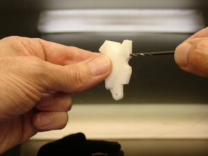
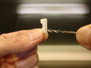
Redrill all the holes on EyeToNose with a 2,5mm drill.
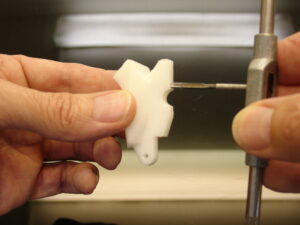
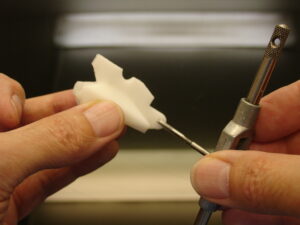
Tab all holes with a tab of 3mm diameter.
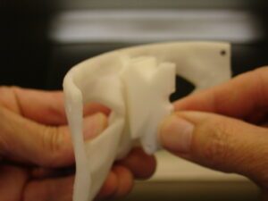
Glue, with acetone if you have ABS prints or Epoxy for PLA, EyeToNose to EyeGlass.
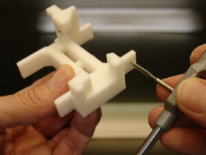
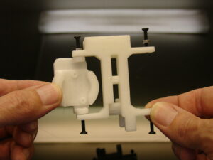
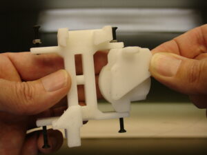
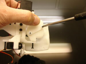
Tab after redrilling the 4 big holes of EyeSupport with a 3mm tab.
Redrill with a 3mm drill the two holes of EyeHolder.
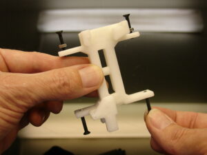
Insert and mount four screws of 3mm. You can add bolts as shown to secure them.
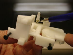
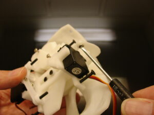
After redrilling the holes of both EyeBallSupport with a 3mm drill, mount them as shown. At this stage you can also add the the Hercules camera on the EyeBallSupport. My picture does not show the mounting of the cameras HerculesHD because I was trying a different sort of camera at the time.
 Here, I am using a LifeCamHD 3000 from Microsoft. The image quality seems less good than the Hercules Twist HD. Notice that the EyeBallSupport is different because the PCB of the camera is set horizontably.
Step2:
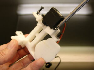
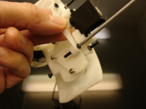
Mount the one DS929HV servos from Hobbyking with its screws.
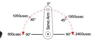
Set the servo at 0 degree with the horn set as shown.
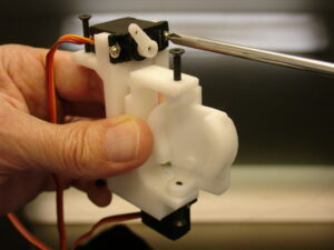
Mount the second servo DS929HV.
Set the servo at 0 degree and mount the horn in a position similar to a 45degree angle.
Add EyeHolder with two screws of 3mm diameter.
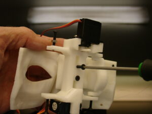
And fix the mecanism to EyetoNose. Once mounted it should be able to rotate freely on its shaft.
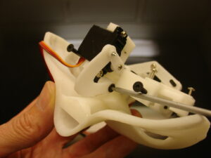
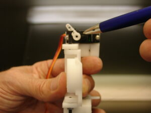
Mount and screw the EyeHingeCurve between the servo horn and EyeToNose. Again the mecanism should be able to rotate freely on it’s shaft.
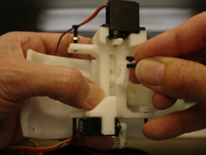
Add on the back of EyeBallSupport the EyePlates. You can either glue them or screw them.
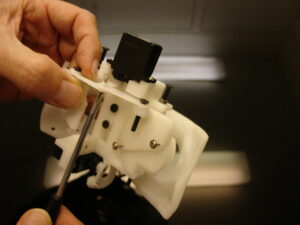
Mount and screw the two EyeHinge between the top servo and the Eyeplates.
Step3:
Now we are going to create some realistic eyes with a few simple steps.
Unmount the mecanism by unscrewing the two screws of EyeToNose to have access to the front of the eyes.
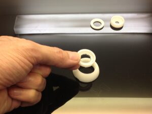
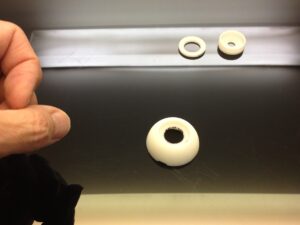
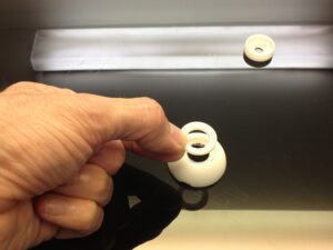
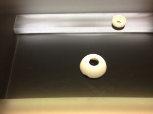
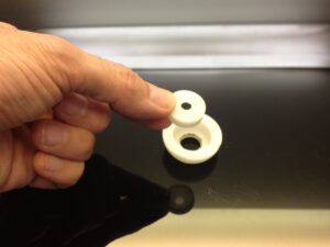
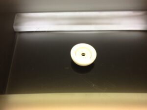
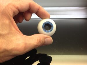
 This is a full EyeBall set.
Bellow is the ring order placement:
Now let your creativity get wild!!
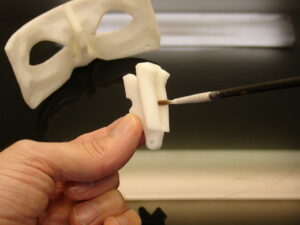
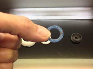 Spray paint or use a colored marker of your choice to create a base on the pupile ring. In my case I used mat blue spray. You can also print the IrisEye file and cut it out.
 Make some little lines with another thin black marker, from center to the outside. Perfection is not required as you can see on my picture. But if you are good and creative, you can really obtain something very realistic.
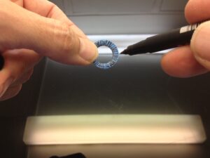
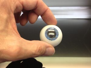
 Add some little lines with your thin marker on this outer ring as well.
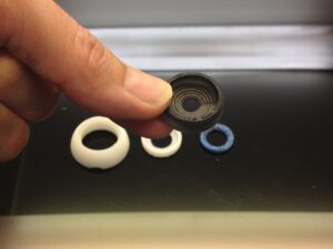 Spray paint in black mat finish the iris ring.
 Now assemble all the rings together.
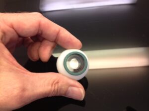 You can also replace the outer ring, pupile, and iris with a Fish Eye Lens for Smartphone. But it looks less realistic.
 To make the eyes even more realistic lets be creative!! Now we are going to create the eye transparent cover.
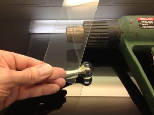 You will need a heat gun, a glass ball of approximately 3 cm diameter (I used the perfume cap « Dior, J’adore » of my wife, fancy eyes!! You also need a piece of thermoformable plastic (cristal clear is better, other wise it will alter the camera vision) I personnaly used a piece of a light bulb blister. But any cristal blister will do the job.
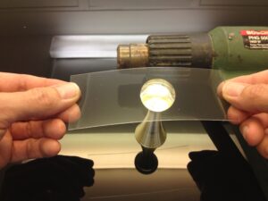 Clean up all the surfaces to make sure you won’t alter the transparent plastic with dust or scratchs during thermoforming.
 Apply hot air on the plastic and when it starts to become soft, apply and stretch it over the glass ball. Wait for cooling.
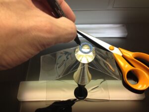 Mark the circle using the pupile ring, and cut out with scissors the lentille.
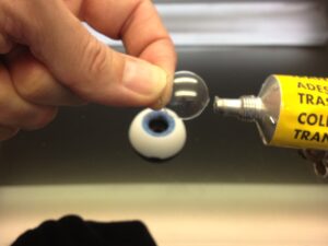 Add a bit of glue on the perimeter, carefull to be clean and avoid finger traces on the inside surface.
 Glue the lentille on the pupile ring. Let it dry.
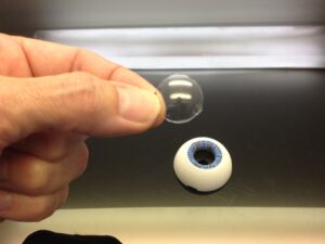
Do the same with the second eye.
Mount back the mecanism on the EyeGlass. There you go, you have an impressive looking InMoov!!!
You are now ready to install the whole face and eye mecanism into the head. See the Hardware map for to check your default servo positions. Make sure no cables are blocking the eye mecanism to rotate in X and Y directions.
Tutorial for the old eye mecanism:
My original STL files are still available here.
I used 3 DS929HV servos from Hobbyking. The two servos mounted for the right/left movement are connected with Y connector, so they receive the same data and act simulteanously.
Some of the pictures in this tuto are showing parts that might be a bit different than the one you actually printed. This is due to different iterations.
Start by screwing the two servos to EyeSupport. In the tuto I have attached only one, but it is best to have two.
Set your servos at 90 degrees using your Arduino.
Attache the actuators of your servos in this position.
Mount EyeCamera part and make sure it can rotate freely on the screw.
Mount the second EyeCamera part
Now add and screw the third servo to EyeToNose
Your part will look a bit different in length.
Be sure to have your servo set at 90 degrees and mount the actuator this way.
Attach EyeToNose to the EyeGlass part
This is a bit difficult because the access with the screw driver isn’t straight.
Now fix EyeMoverSide through EyeCamera to the actuator of the servo. You can also mount a second servo instead of using EyeMoverSide.
two servos makes the X movements more sturdy.
Repeat this on bothe eyes.
Mount EyeMoverUp, it should NOT be tight screwed
Fix this assembly to EyeToNose, going through the eye space is an option to make it easier.
Fix the EyeMoverUp to the bottom servo actuator.
Normaly your mechanism should be ready for movements.
Making test with your Arduino is a good thing at this point. Be sure to start with small range degree movements, especially for the up and down movement. You can start with 30 to 120, it should be fine.
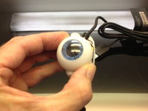
What follows is what I did to make the cameras look more like eyes.
I used a ping pong ball cutted with a knife and small scissors.
The hole where you insert the lens can be rounded up with sand paper, because cutting a clean hole with a knife isn’t easy.
Adjust the hole precisely to your lens and PCB board
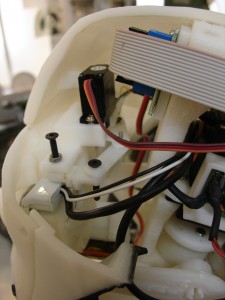
I used a piece of heavy tape to cover the back of the PCB, for two reasons:
First to avoid using hot glue directly on the components and also to shutter the back of the lens to keep it dark (Oddly light coming from the back of the lens interfer with the image received by the camera.)
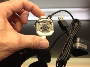
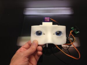
Now you can mount it to the head. You can see here my two different cameras.
On the left the Megapixel and on the right the Hercule twist.
The connections of these three servos will be added on the Arduino board, once the InMoov service will be implemented for that.