
Print wristarge, wristsmall, Thumb, with an infill of 30%, 3 shells, best with no support, no raft.
Print index3, majeure3, ringfinger3, auriculaire3, with an infill of 30%, 1 shell, best with no support, no raft.
Print robpart2, robpart3, robpart4, robpart5 with an infill of 30%, 3 shell, best with raft, no support.
Print coverfinger with an infill of 30%, 3 shells, with support. To get the best printing result on the covers is to print them standing up, instead laying them flat.
The wrist parts are good printed with an infill of 30%, 3 shells, with no raft, no support. The Gears of the wrist should be printed with the best quality your printer can give you.
Big bolts are now printable. (Strong enough for tests and even more!)
You can replace the 16x3mm for the fingers with pins/pegs of filament instead of bolts, it’s cheap, easy, and strong enough. It was a suggestion of FreddyA.
- 1x8mmx8cm bolt to attach wristlarge to wristsmall.
- 1x8mmx4cm bolt to attach wriarge to thumbbottom.
- 1x8mmx6cm bolt for to attach wriarge to robpart1.
- 16x3mmx2cm bolts for all fingers hinges(I have recut each bolt to adapt to finger width)
These instructions are for the right hand. The left hand is similar but parts are mirrored.
Step1
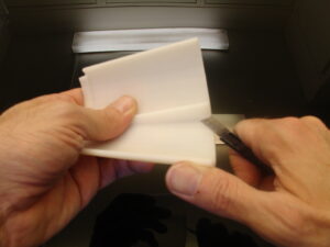 Remove the antiwarp supports and trim with a knife, RobPart2, 3, 4 and 5
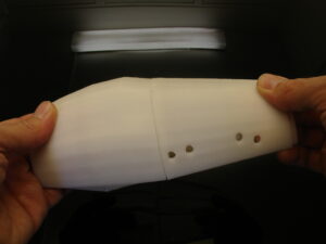 Assemble together Robpart2 and Robpart5
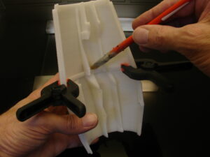 Help yourself with pliers to hold the parts together while you glue them with Acetone (ABS) or Epoxy 2 components(PLA)
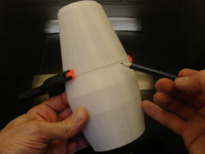 Avoid using glue on the outside other wise it won’t look clean. Control that your parts are correctly aligned.
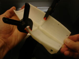 Do the same with Robpart3 and 4.
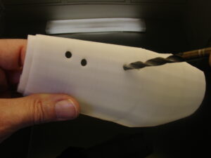 Redrill the holes on the side of Robpart2 with a 6mm drill. These are for to fix an extra servo to get a double actuated thumb. See: http://www.thingiverse.com/thing:28124
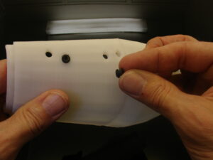 Use the little rubber silentblocs that came with your servos.
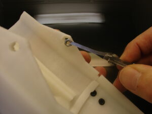 In Robpart5, insert two bolts for 4mm screws in the printed cavities. Mine were not fitting, due to overhang, I heated them with a flam to make them fit.
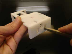 Trim/Fill the holes of the simple servo bed if there is overhang.
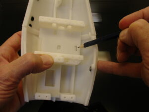 Set in Robpart5 the simple servo bed, make sure it is completely seated on the bottom.
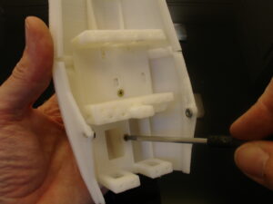 Glue or screw the simple servo bed with 2 wood screws.
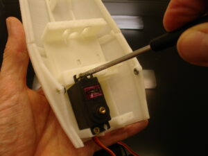 At this point we can mount the servos on simple servo bed.
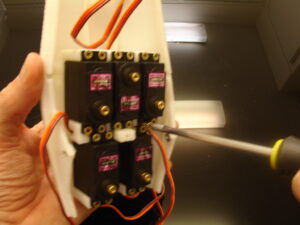 As you can see on my picture, I’m not using the HK15298 but some MG946r instead, for this tuto. The reason is that Hobbyking Europe is out of stock and I couldn’t wait.
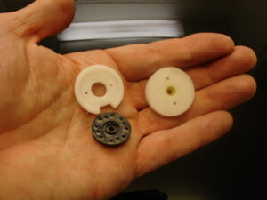 When you download my parts on Thingiverse, you can either choose to print RobRing or ServoPulley. It all depends, if you received with your servos the black actuator shown in my hand.
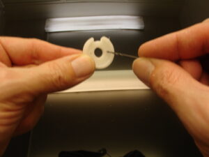
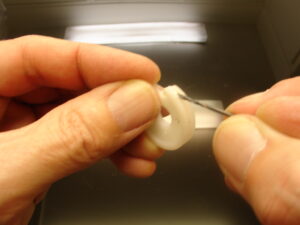 I personnaly use the ServoPulley. Redrill the holes with a 2mm drill.
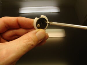 Use the screws that came with your servos to mount the black actuator.
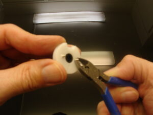 Cut the screws in the back with cutters.
Now use this script with your Arduino to set all your servos at 90 degrees. Set screw all the ServoPulleys in place as shown. Once the ServoPulleys are fixed, using the script again, set all the servos to Zero degrees. This will be for later when we attach the fishing lines. Avoid moving them during the next steps, otherwise you will need to reset them to Zero later.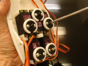
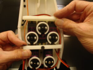 Mount on Simple servo Bed, RobCableFront and RobCableBack.
Step2
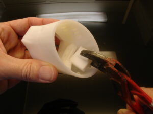 On RotaWrist1 remove the support.
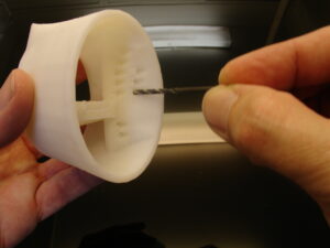 Redrill if necessary the holes for the lining.
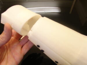 Make sure it fits on the Robparts.
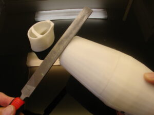 You can use a fill to adapt it perfectly.
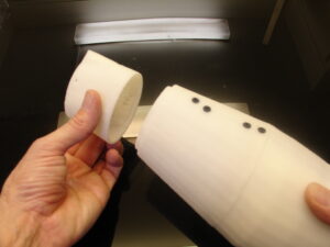 This is the correct way to mount it, see, the black holes are aligned with the squary part of RotaWrist1. I have seen many assembly where the wrist was mounted the opposite way.
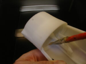 Back to RotaWrist1. Glue it to Robpart2. When doing this it is good to also set the Robpart3/4 cover to make sure the RotaWrist1 is correctly placed.
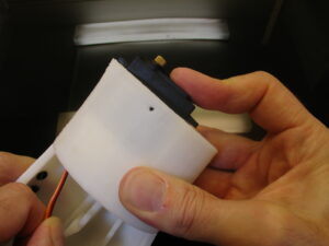 Insert your MG996 servo. Here we want a servo with 180 degree rotation. The HK15298 only rotates of 90 degrees.
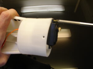 Set the wood screws to fix your servo in place.
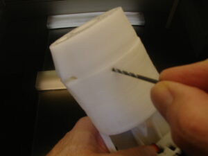 Redrill with a 2.5mm drill RotaWrist2.
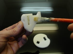
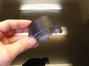 I like to spray paint in black RotaWrist2 because the grease used inside makes the part become yellow after some time.
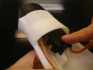 This picture is to show where to set the extra servo if you use the thumb with double actuation.
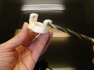 Redrill with 8mm RotaWrist3.
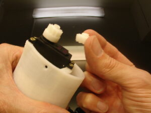
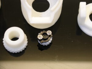
With your downloads there is two different small gears, use the one you think is most appropriate for your needs. Here is a previous tuto you might want to read.
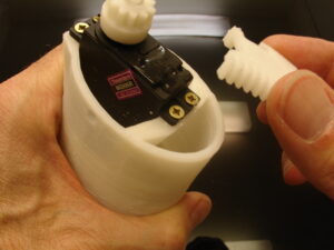 Use Epoxy two component glus to fix CableHolderWrist on the servo.
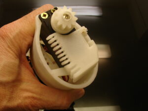
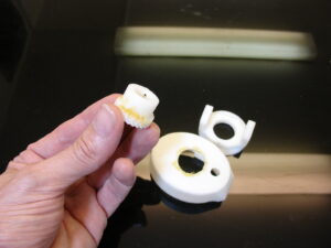 Use grease between the components.
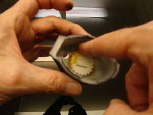
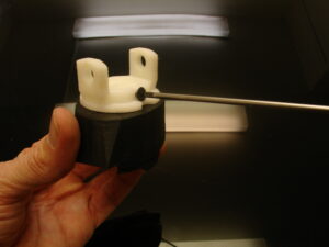 Mount RotaWrist3 to the big Gear.
Step3
See also this tutorial to create silicone finger tips.
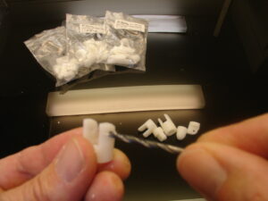 Time to redrill the finger hinges. I keep the fingers in seperate bags to avoid mixing them.
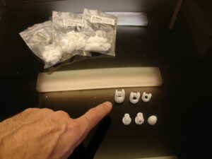 The outside hinge is redrilled with a 3mm drill.
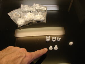 The inside hinge is redrilled with a 3.2 or 3.5mm drill.
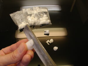
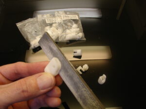 Fill the hinges to really adapt them the best.
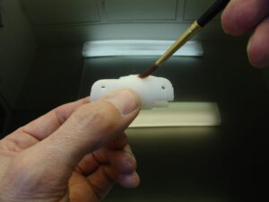 Glue the parts together with Acetone(ABS)
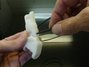 Use your 3mm filament to make pegs.
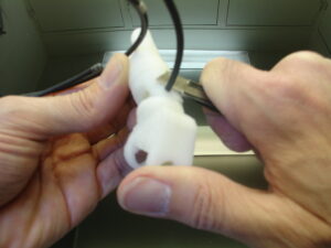 Cut with a knife the filament. If you don’t have 3mm filament you will need to do this with bolts of 3mm. I recommand the filament, it’s perfect, cheap and fast.
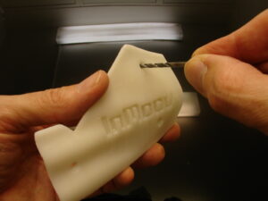 Redrill all holes of the covers with a 3mm drill.
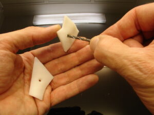
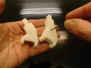
Redrill Wristmall and Wristlarge with a 2.5mm drill for to adapt the covers. If you don’t have exactly these size of screws, it doesn’t really matter. Use whatever you find at you hardware shop. Remember that the covers have a purpose and are necessary to have a correctly functional hand. They restrain Wristmall from going to the back of the hand. If you don’t understand read this.
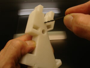
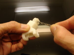
Redrill the hinges of Wristmall and Wristlarge with a 3.2 or 3.5mm drill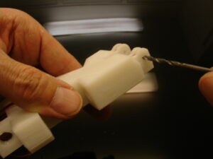
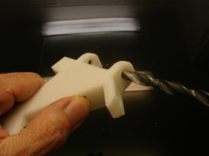 Redrill the big hinges with a 8mm drill.
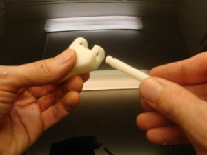 Ensure Bolts or printed Bolts run smoothly with no resistance but without wobbling.
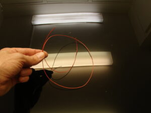 Cut 10 pieces of 75cm long of your braided fish line 200LB. Don’t use standard nylon because it stretchs.
At this point it is good to decide if you want to have sensors on the tip of the fingers or not. You must have seen three holes above each other for the linings in WristLarge. The third hole (middle one) is for running electrical cables to wire up the sensors.
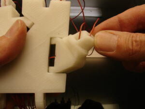
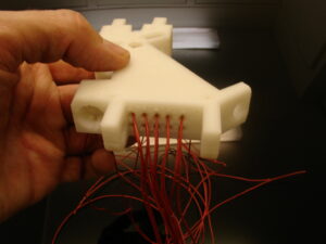 Insert the braided fish lines in the holes of Wristlarge. In this picture, I don’t have electrical wires for sensor fingers because it was a previous version.
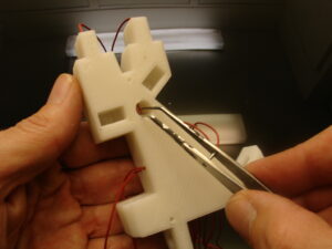 I have designed a little hole which can help you to guide the linings.
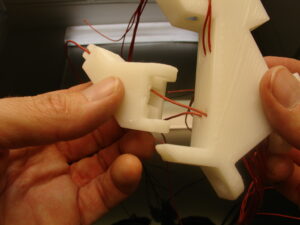
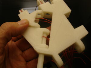
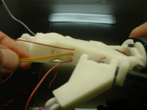 The electrical cables are running in the middle holes.
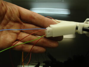 Run the linings into Wristmall. Make sure not to twist them on the way through. If you mix them up, the servos won’t be able actuate the fingers correctly.
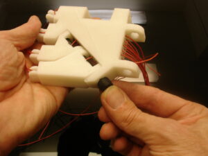
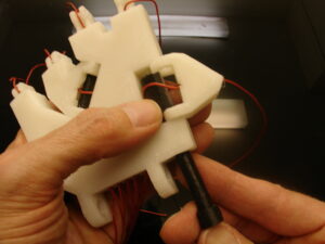 Repeat the wiring with the thumb. If you are using electrical cables don’t use the « Entretoise », as shown above, otherwise you won’t be able to run the electric cables.
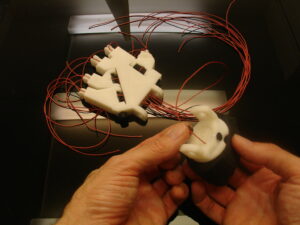 Line up the hand to the wrist.
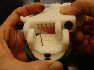
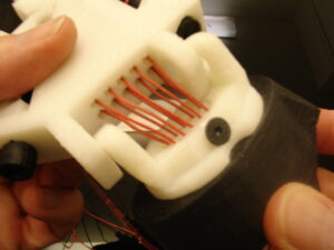
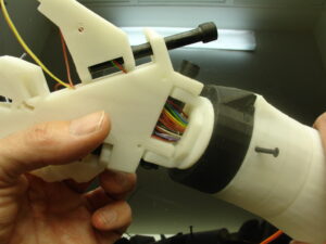
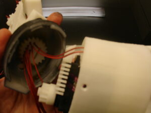 Now wire up the Wrist to the forarm, each lining has a slot.
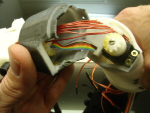 If you have electrical cable it will be like this. Using color ribbon is a good idea because you know what wire correspond to which finger and connection.
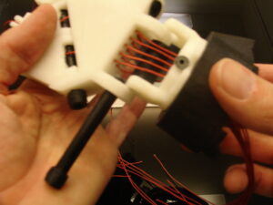 Add the « Entretoise » between the cables
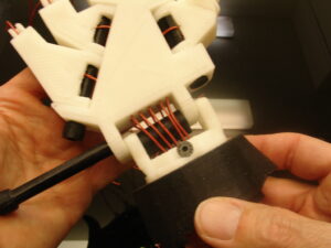
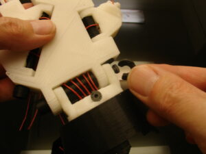 Use the « C » ring to end stop the bolt from coming out.
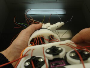
 This is the back of the hand, you can see how I have set the cables. I’m not sure it is the best solution but, like you, I’m learning and discovering.
 Here is how the lining should look up to the wrist.
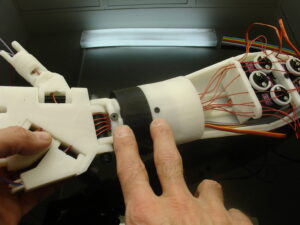 When you assemble the wrist make sure the servo is set at 90 degree and that the two screws on the picture are aligned. Until now I never did recomandation about this, and unfortunatly many of the gestures I created can’t be reproduced by other InMoov because the wrist isn’t set the same than mine.
 Glue RobCap to ElbowShaftGear.
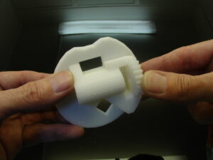 Aligning the squarry hole is the way to do it. If are using ABS and acetone, I can tell you there is no need to add screws if both of your surfaces are correctly flat.
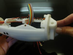 Now glue this assembly to RobPart5, make sure it is correctly aligned in the slots.
Step 4
When assembling the fingers there is marks that can help you to see in which order it has to be done. I won’t go in those details here but you can find more instructions in the finger starter tutorial. The finger starter has numbers for an easy comprehension, the normal fingers don’t have those numbers, but the parts are the same.
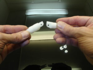
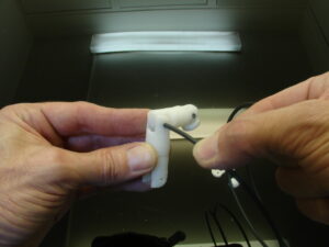 Now that you have all your fingers assembled, for those that want to add sensors here is how we are going to proceed.
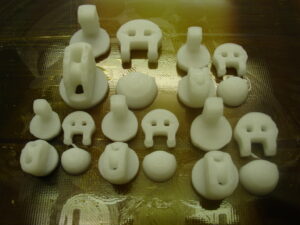 Finger sensor prints.
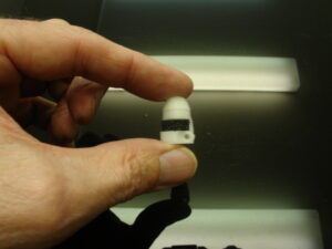
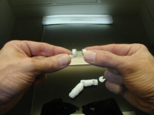 Glue the tip of the finger to the hinge tip. Make sure to align the nail lines, it will look better 🙂
 Sorry for the blurry picture.
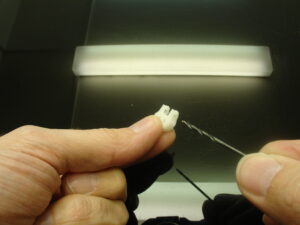 Redrill the holes of the hinge with a 2mm drill.
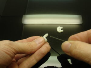 Redrill the hole of the tip hinge with the same bit.
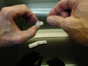 Add the hinge to the tip hinge and redrill them together to make sure they fit nicely.
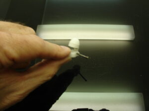 I used non flat metal nails instead of filament here, because the size of these parts are small. I just cut them at the size needed.
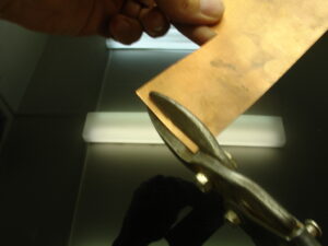 Cut some strips of copper of about 3 to 4mm large.
 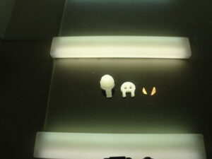 Recut those strips in tiny triangles. These are going to be contactors for the antistatic foam.
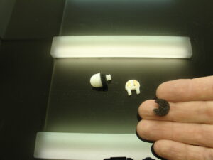 Cut with scissors some nice little rounds in your 4/5mm thick antistatic foam. This foam is sold with electronic components to avoid electric shocks. Most of the time we just throw it away when we buy components, you can also buy it in many electonic shops. It contains carbon which is an electrical conductor. When the foam is pressed against the 2 contactors, the carbon lets the current flow between them. More the foam is pressed and more current goes through. This is the info we will send to the Arduino Analog pins.
Glue with 2 components epoxy the foam to tip hinge part as shown on the picture.
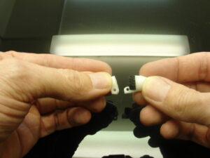 Try to assemble the two parts and see if it move. The hinge design is supposed to stop the hinge from opening further than the 5mm thickness of the foam.
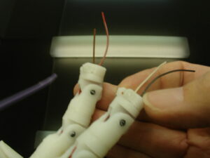
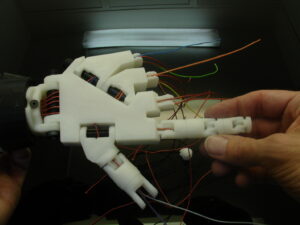 Time to mount the finger to Wristlarge. Notice the last hinge of the finger, this will receive the finger tip sensor assembly. All the holes in those finger parts should be cleared and large enough to have the 2 tension cables and the 2 electrical cables.
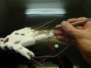 Run the tension cables and the electrical cables. One of each on the up side and one of each on the down side. Make sure to avoid any twisting of cables, this would cause to get unfunctional fingers.
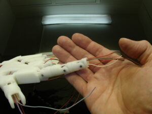 The color ribbon again is handy in this task.
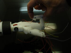 Fold the fingers to smooth up a bit the cables in their path.
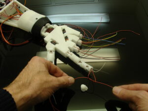 Make knots with the tension cables.
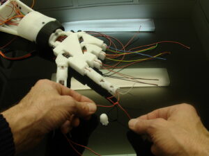 A bunch of them is necessary because we don’t want them to go through the holes when the servos are pulling hard on them.
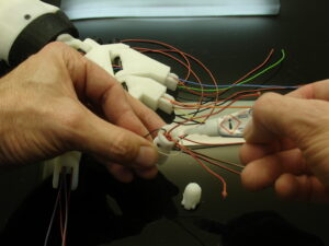 What I do is even add glue to ensure any bad surprise. I also glue the electrical cables at the same time. When doing so, it is good to have the finger folded otherwise the electrical cables could later restrain the full motion of the finger.
 Cut the remains of the tension cables. Now glue the hinge of the finger tip to the last hinge of the finger. Notice the position, don’t glue them upside down. Remember I mentionned the tip hinge was design to avoid opening further than the thickness of the foam.
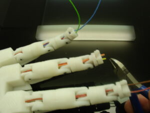 Cut each electrical wire at a 4/5mm length. Scary moment because too short would mean to redo all the wiring. 🙂
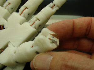 Cut and clear up the plastic on the electrical cable and solder the copper triangles.
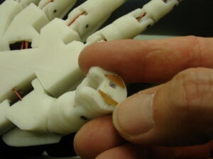 Once done, fold the cable and lay the copper triangles in a flat position.
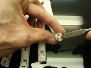 Add 2 component glue under.
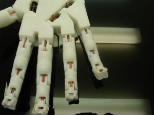 To maintain them flat during the time the glue gets hard, I used some tape, Look out for the tape you use as it maybe glued as well to the finger tips.
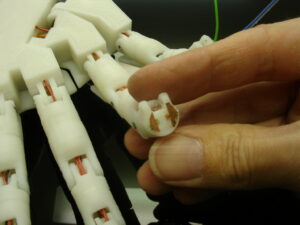 This is the result.
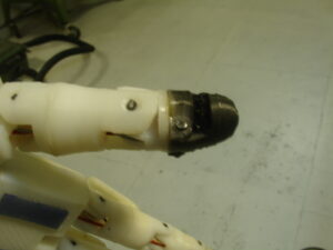 Now you can add the finger tip with the nail and you should have a sensor ready to be pressed and give feedback.
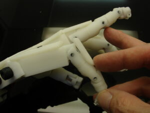 Glue the finger covers on the fingers.
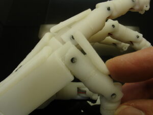 These are used to avoid the finger going to much in a backward position and they also add a llok to the design 🙂
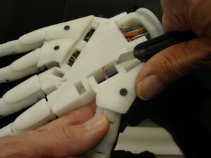 Do the same with the Thumb cover and Wristsmall. Actually I glue them first and then I add the screw, that keeps them well in place. Recut with a knife the two corners on the thumb hinge. If you don’t the hinge will be forcing against the hand cover.
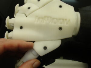 Add the hand cover and check if the fingers are moving nicely.
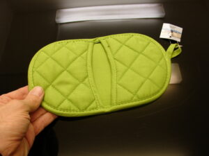
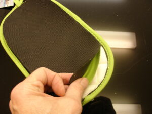
You can add Sugru on the finger tips or see this tuto, and ping pong surface in the palm of the hand for a better gripping. I found also some kitchen heat protectors for 1,50 euros with silicone surface. It is even better.
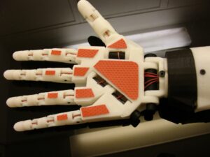
Hey it looks like you are set to tension the fishing braided lines!!
In the next tuto there is steps I’m going through again and they might also look a bit different. The reason is because of updates. Actually the next tuto was done before the tuto you just followed above.
You never used Arduino before, use this introduction.pdf or find more info on the Finger Starter tutorial
Go to this tutorial for tensioning the Linings.
Go to this tutorial to create your silicone finger tips.
Using MyRobotLab with a minimal script