This tutorial is about the assembly of the Mid Stomach parts.
Beware that these parts will certainly be obsolete and temporary once the legs are done. I post them anyway because many builders asked for them. There is pictures missing in this tutorial, I lost them with a hard drive…
Download STL files from the Gallery
Before printing all the parts you should print the CALIBRATOR, to check if your parts will fit together. If you have a very hard time putting those parts together, adjusting the horizontal expansion setting of your slicer software can solve that, this setting can vary depending of your slicer and printer but users report to set it at -0.15 is a great place to start.
An infill of 30%, wall thickness 2.5mm, best with no raft, no support(unless specified), use a brim for big parts to avoid warping.
You will need to print all these parts:
- 1x BotBackLeft
- 1x BotBackRigt
- 1x BotCapLeft
- 1x BotCapRight
- 1x BotFrontLeft
- 1x BotFrontRigt
- 1x HipCoverFront
- 1x HipCoverLeft
- 1x HipCoverRight
- 1x MidPotHolder
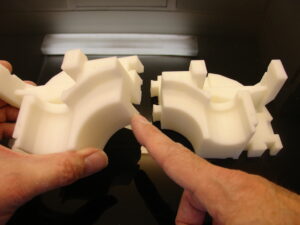
- 2x MidWormRight
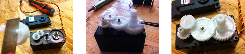
You will need 2 servos HS-805bb which needs to be hacked. Both motor servos will be using only one servo board and one potentiometer, this way both motors will be synchronised when rotating. This will be explained in the tuto.
You will need between 65 to 70 ball bearings. You can use steel or BB Gun balls. They should be 6mm diameter.
I tried to use Vigor VSD-11AYMB servos and made some files files adapted for it. Unfortunately these servos aren’t good because they jitter sometimes. Another annoying factor is that they won’t « detach » properly through software.
Step1: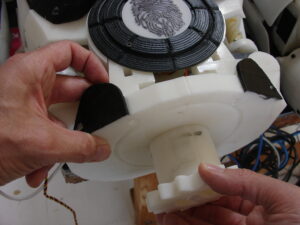
Check that StomGearV2.stl fits correctly into the Top Stomach parts.


Also make sure that StoGearAttachV1.stl seats well on the bottom surface of the Top Stomach parts. For more info check the tutorial on TopStomach.
Step2:
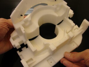
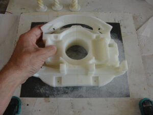
Assemble together BotBackLeftV1.stl , BotBackRigtV1.stl , BotFrontLeftV1.stl , BotFrontRigtV1.stl.
It is best to glue them together laying on a flat surface.
There is also the option to mount bolts for those of you that prefer.
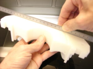
Make sure the flat surface is as flat as possible.
If the surface is too uneven, glue a sheet of sand paper with double side tape on a flat board, and sand down your assembly until you are satisfied.
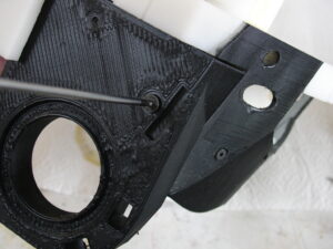
Smooth up the surface where the ball bearing will take place. I personnaly used Acetone because my parts are printed in ABS.
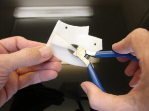
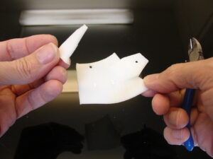
Cut off the pre-support on the HipCoverFrontV1.stl.
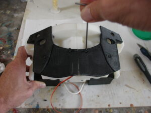
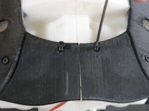
Mount with 3mm screws the HipCoverFrontV1.stl to your assembly. In my case I sprayed the black parts with car aerosol mat finish paint using masking tape.
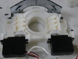
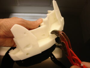
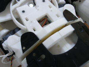
Mount the two MidWormRightV1.stl to the servo horns with screws. Fit the servos on your assembly using wood screws. The connection wires of the servos will be detailed later in step3.
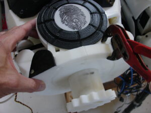
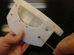
At this stage it is a good idea to make sure StomGear fits well through your assembly.
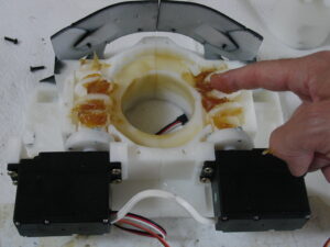
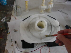
Put a good load of greaseon the wormgears and in the passthrough hole for StomGear.
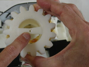
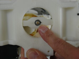
Check the potentiometer hole on StomGear and position it as shown.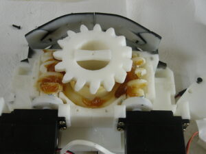
Fit in StomGear.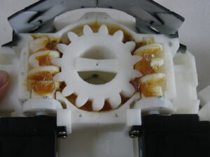
Make it go all the way through your assembly.
Step3:
Hacking the servos
You will need to remove the potentiometer from your servos as described in this tutorial. Remember that the Vigor VSD-11AYMB servos are slightly different than the Hitec805BB. The below tuto explains for Hitec805BB.
The two servo need to be hacked for continous rotation.
One of the two servo will be controlled by the other so you have to remove the board and potentiometer of this servo (keep it preciously for spare part as if one day you burn a 805B servo controller board).
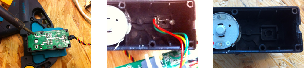
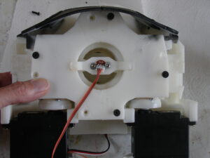
Three welding to remove to detach the servo controler board and the square potentiometer
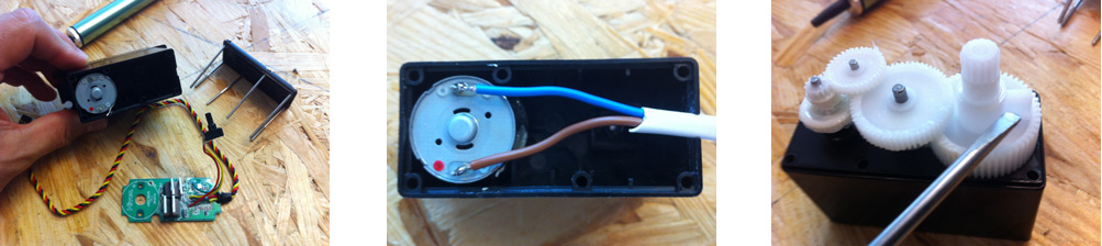
Weld two Wires directly on the motor, dot red point for positive (I suppose).
and cut as usual the small piece that block the full rotation of the servo motors.
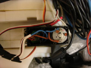
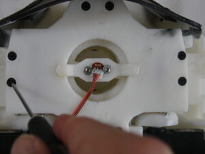
Set the blue cable on the positive side of the motor (red dot)
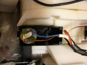
On the other motor, set the brown cable on the positive side of the motor.(red dot)
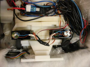
Make sure you have reversed the color cable to the motor polarity. This way one motor will turn one way and the other will turn the other way.
Step4:
Missing pictures: Assemble together on a flat surface BotCapLeftV1.stl and BotCapRightV1.stl . Use Acetone if ABS prints or Epoxy if PLA prints.
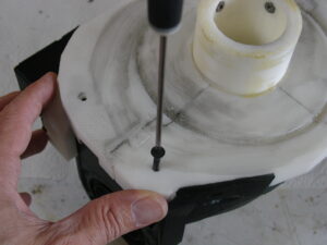
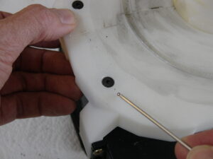
Mount the potentiometer on MidPotHolderV1.stl, respecting the small metal positioner. Glue MidPotHolderV1.stl to the BotCap.
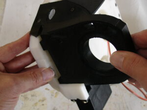
Set the BotCap assembly on the main assembly.
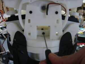
Use 4mm screws to fix BotCap to main assembly.
Mount TStoLowLeftV1.stl and TStoLowRightV1.stl to your main assembly.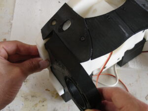
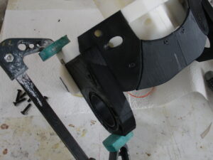
Using a clamp to press fit will ease the job.
Add 4mm screws, making sure the screw head is well sinking into the part. Otherwise it will restrain rotation between TopStomach and MidStomach.
Add screws on the sides as well.
Step5:
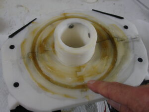
Add a good load of grease on your assembly flat bed.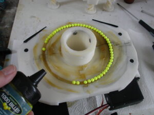
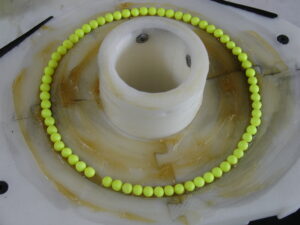
Add some 6mm ball bearings, I used BB Gun balls which do the job quite well until now.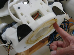
Apply grease on the flat bed of TopStomach as well.
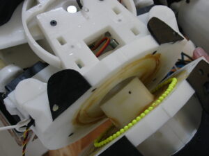
Fit in the StomGear to assemble TopStomach and MidStomach together.
Use 4 screws of 4mm to fix StomGearV2.stl to StoGearAttachV1.stl as already seen in the tutorial of Top Stomach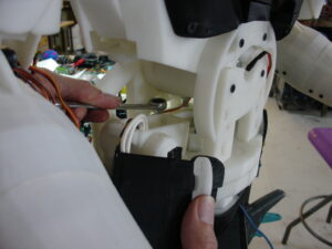
Adjust the bolts to make sure TopStomach and MidStomach are well tight. But don’t overtight because we want to keep these parts some freedom for rotation.
Time now to run some script test to see if all is set in order.