My tuto isn’t finished at all, the pictures aren’t sorted in the correct mounting order, so for now it is up to you to find your way through.
But David has done and kindly shared a tutorial, you will find it under all my pictures.
Download STL files from the Gallery
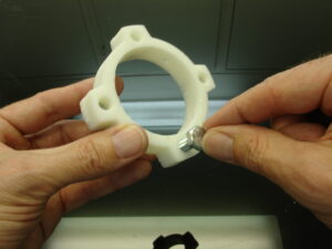
Before printing all the parts you should print the CALIBRATOR, to check if your parts will fit together. If you have a very hard time putting those parts together, adjusting the horizontal expansion setting of your slicer software can solve that, this setting can vary depending of your slicer and printer but users report to set it at -0.15 is a great place to start.
An infill of 30%, wall thickness 2.5mm, best with no raft, no support(unless specified), use a brim for big parts to avoid warping.
You will need to print all these parts:
- 1 x DiskIntern
- 1 x TStomSpacer
- 1 x TStomRotFront
- 1 x TStomRotBack
- 1 x TStomPotHolder
- 1 x TStomCovRight
- 1 x TStomCovLeft
- 1 x TStoServoHolster
- 1 x TStoPistonRight
- 1 x TStoPistonLeft
- 2 x TStoMiddle
- 1 x TStoFrontStand
- 1 x TStoFrontRight
- 1 x TStoFrontLeft
- 1 x TStoBackStandRight
- 1 x TStoBackStandLeft
- 1 x TStoBackRight
- 1 x TStoBackLeft
- 1 x StomGear
- 1 x StoGearAttach
- 1 x ServoBack
- 1 x RollFrontRight
- 1 x RollFrontLeft
- 1 x RollBackRight
- 1 x RollBackLeft
- 1 x DiskUnder
- 4 x DiskExtern
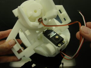
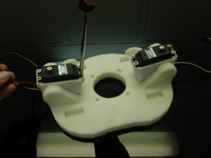
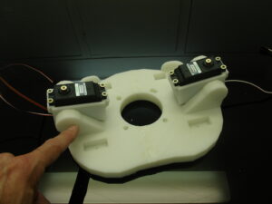
You will need 2 servos HS805BB which needs to be hacked. Both motor servos will be using only one servo board and one potentiometer, this way both motors will be synchronised when rotating. This will be explained in the tuto.
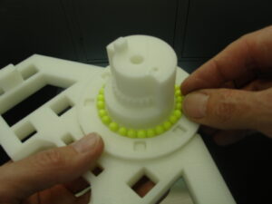
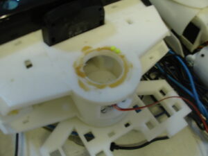
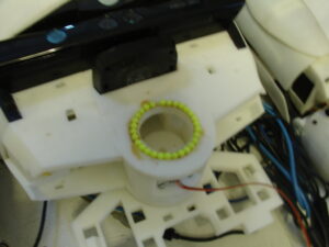
You will need approximately 50 to 60 balls of 6mm diameter to create the bearing. Steel or plastic for BB Gun.
You will also need (for the fun) 1 Neo Pixel Ring from Adafruit. As for now I’m using an extra Nano Arduino board to control it, but hopefully this will be implemented into MRL and we will be able to connect it to our Mega board.
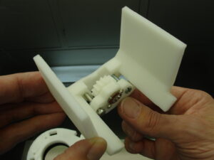


Top Stomach tutorial done and shared by Sebastien
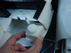
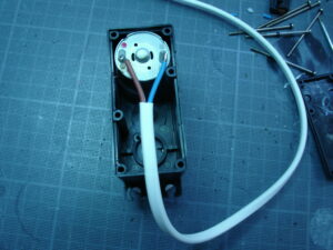
The two servo need to be hacked for continous rotation.
One of the two servo will be controlled by the other so you have to remove the board and potentiometer of this servo (keep it preciously for spare part as if one day you burn a 805B servo controller board).
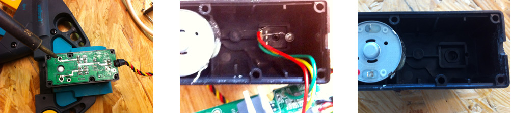
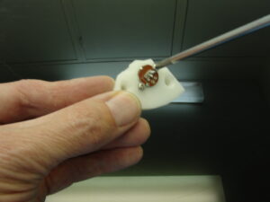
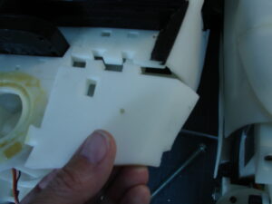
Three welding to remove to detach the servo controler board and the square potentiometer
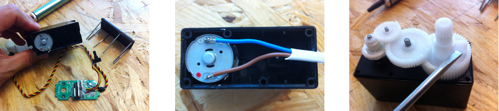
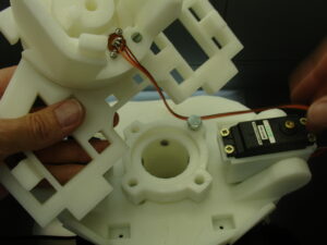
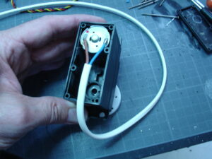
Weld two Wires directly on the motor, dot red point for positive (I suppose).
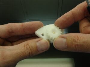
and cut as usally the small piece that block the full rotation of the servo motors
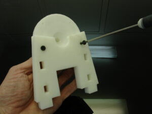
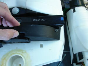
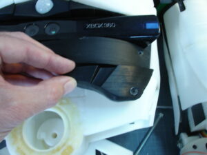
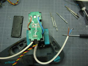
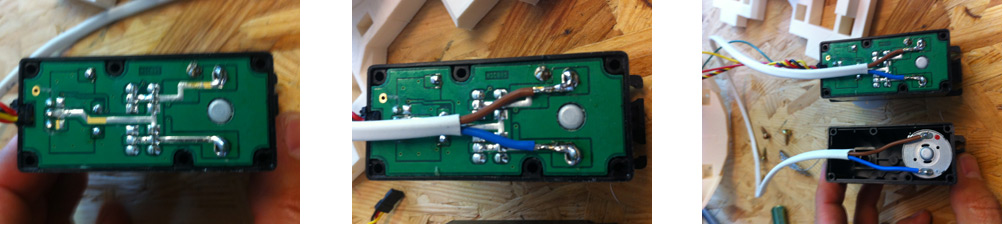 On the second servo motors weld the 2 wires on the board like this. Be carefull to set sale color cable to same position
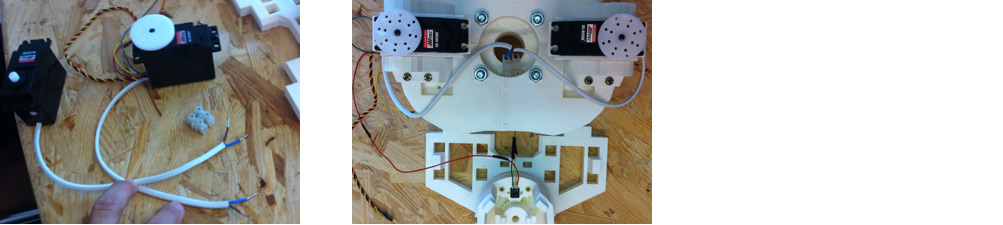
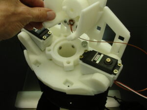
I need to cut the white link cable to mount the 2 servos on their holder. Also better if one need to be replaced.
If all is ok, a quick test with the sweep example script on arduino should produce what you can see on this vidéo…
Top Stomach tutorial done and shared by David
Here is the order I printed the parts:
Step 1
- 1 x RollFrontRightV1.stl
- 1 x RollFrontLeftV1.stl
- 1 x RollBackRightV1.stl
- 1 x RollBackLeftV1.stl
Step 2
- 1 x ServoBackV1.stl
- 1 x TStoServoHolsterV2.stl
Step 3
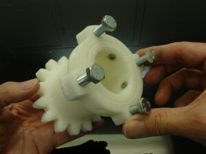
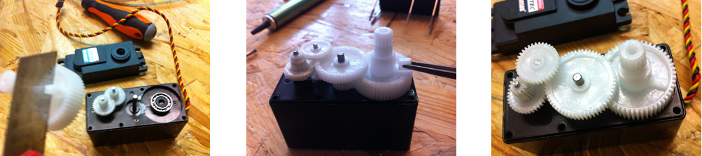
- 1 x StomGearV2.stl
- 1 x StoGearAttachV1.stl
Step 4
- 1 x TStoBackStandRightV1.stl
- 1 x TStoBackStandLeftV1.stl
- 1 x TStomRotBackV1.stl
- 1 x TStoBackRightV1.stl
- 1 x TStoBackLeftV1.stl
- 1 x TStoMiddleV1.stl
Step 5
- 1 x TStoFrontRightV1.stl
- 1 x TStoFrontLeftV1.stl
- 1 x TStoMiddleV1.stl
- 1 x TStomRotFrontV1.stl
- 1 x TStoFrontStandV1.stl
- 1 x TStoPistonRightV2.stl
- 1 x TStoPistonLeftV2.stl
- 1 x TStomCovRightV2.stl
- 1 x TStomCovLeftV2.stl
- 1 x TStomPotHolderv1.stl
- 1 x TStomSpacerV1.stl
Step 6
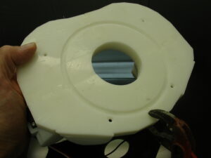
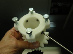
- 1 x DiskInternV3 .stl
- 1 x DiskUnderV1.stl
- 4 x DiskExternV2.stl
You will also need the following:
2 servos HS805BB, 6mm bb bullets can be used or 6mm steal ball bearing
You will also need 1 Neo Pixel Ring from Adafruit
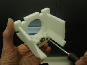
Metal bolts M4x16 – M4x25 – M8x35 – 4 pieces
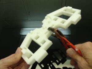
Step 1
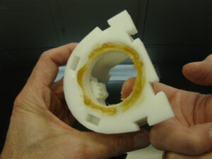
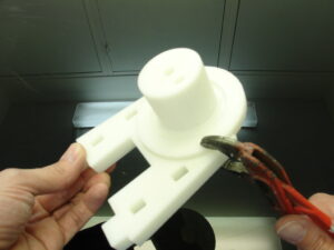
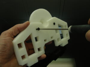
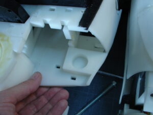
Print the following parts: RollFrontRightV1.stl, RollFrontLeftV1.stl, RollBackRightV1.stl,
RollBackLeftV1.stl, you have to put them together as shown in the picture below, the parts
should fit together without the need of glue (they don’t usually need rasping but if you are
having trouble fitting them you can rasp a bit, but I don’t recommend, if you printed it with
the correct settings it should fit, tightly but fit), however you should glue it together if the
connection is loose (keep in mind that you can glue parts when all is put together).
Discover pictures of all the parts and steps on David album