Download STL files from the Gallery.
Before printing all the parts you should print the CALIBRATOR, to check if your parts will fit together. If you have a very hard time putting those parts together, adjusting the horizontal expansion setting of your slicer software can solve that, this setting can vary depending of your slicer and printer but users report to set it at -0.15 is a great place to start.
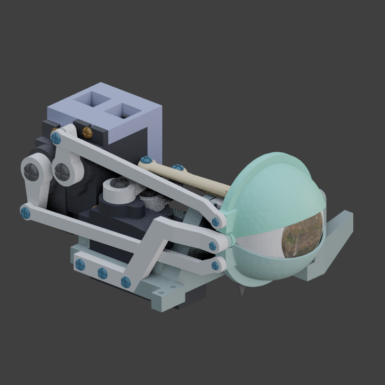
i2Eyes printed parts for 1 Right Eye:
Here is the list of parts and the number of prints needed for the head:
Print with an infill of 30%, wall thickness 2mm, if your printer is well calibrated there is no support required.
i2Eyes tutorial
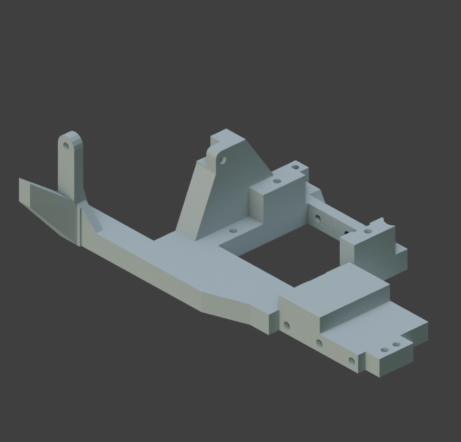
Assemble together the main shaft to the base.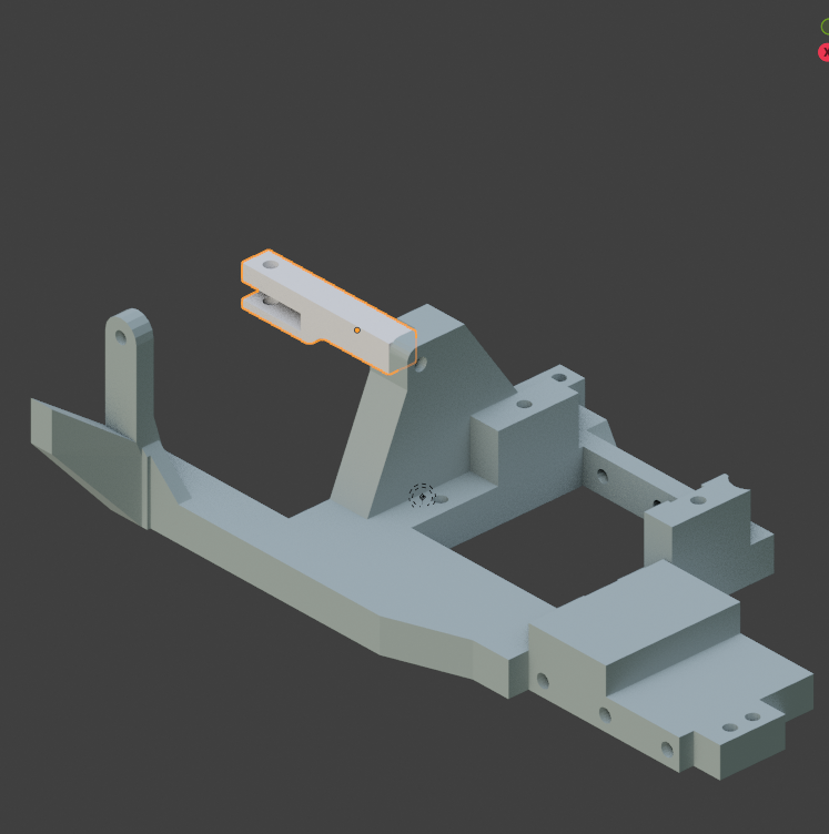
Glue or use a 2 x 6mm Self Tapping screw to maintain together the main shaft to the base.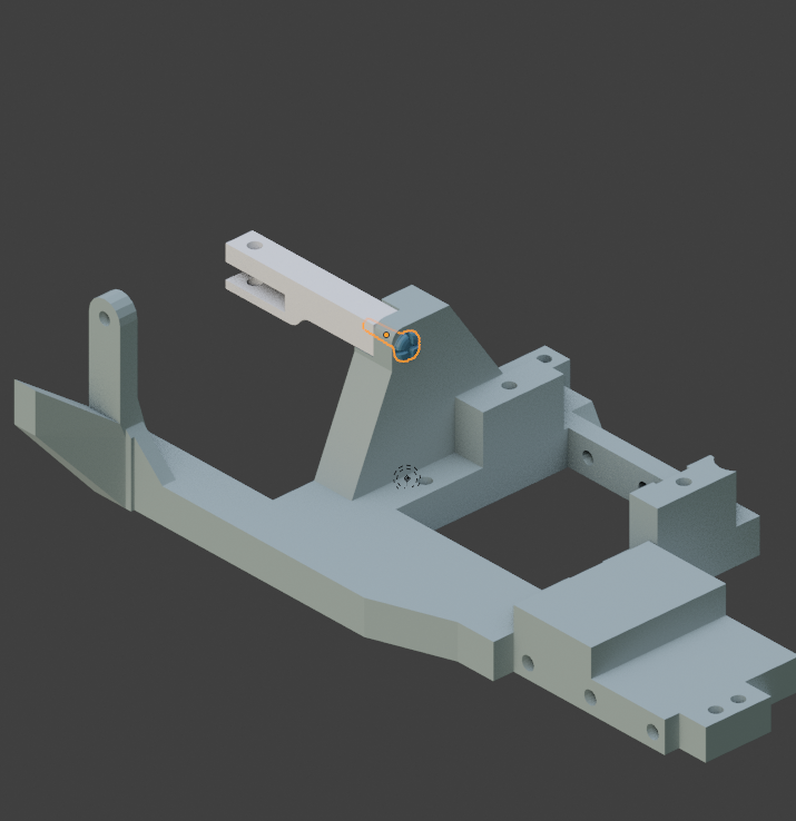
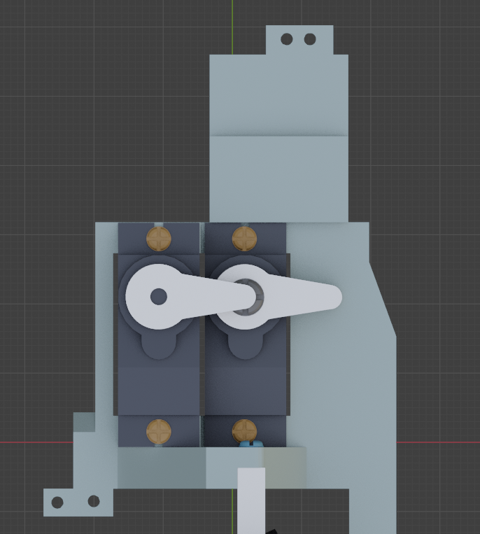
Press in to the base, two servos and make sure they are preset at 90° in your software.(rest position) .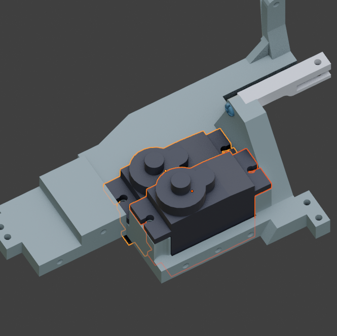
Use 4 screws Self Tapping 3 x 10mm to fix the servos to the base.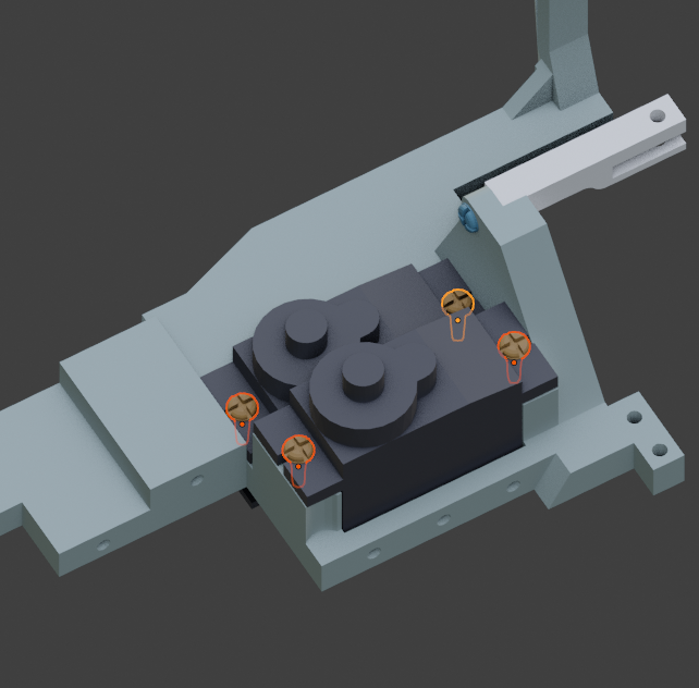
Mount the first horn.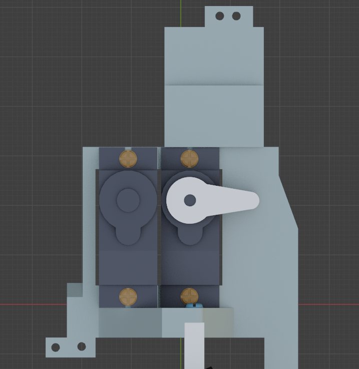
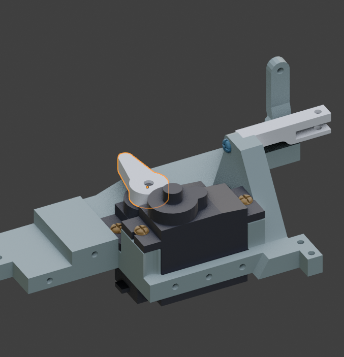
Use the 3mm screw supplied with the servo to fix the horn.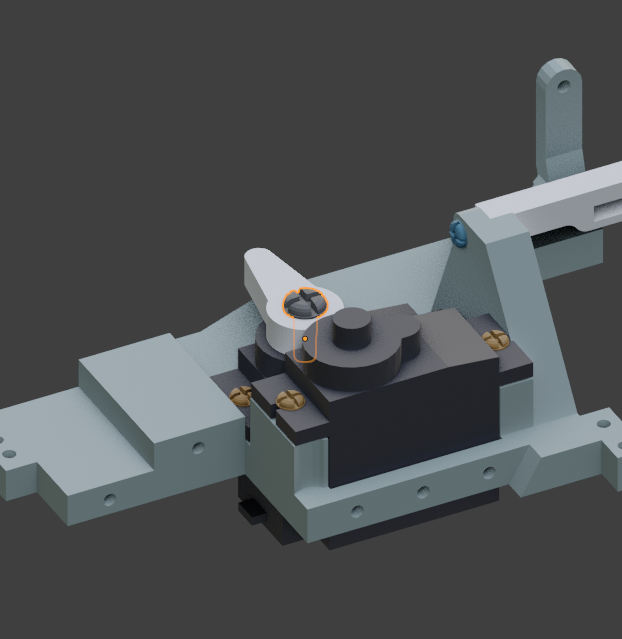
Mount the second horn.
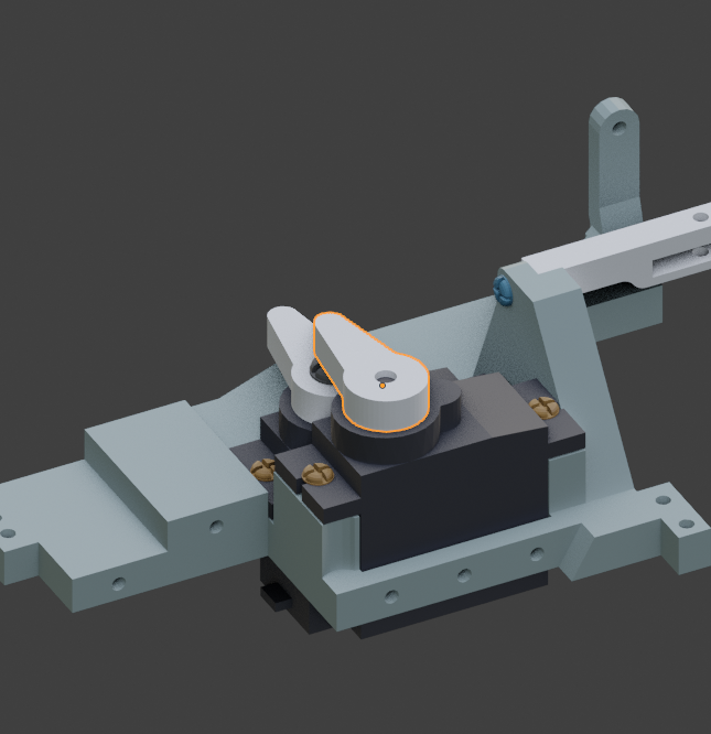
Use the 3mm screw supplied with the servo to fix the second horn.

Add the side arm to the base.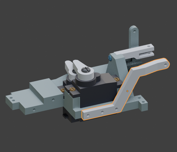
Glue or use 3 Self Tapping screws 2 x 6mm to fix the side arm to the base.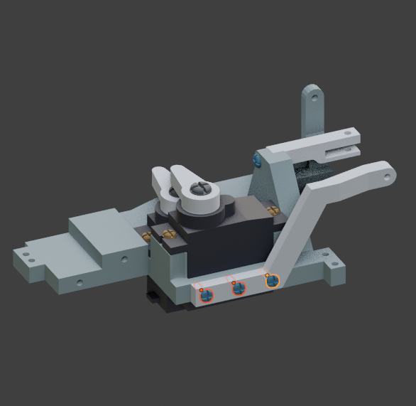
Add two servos to the side base. Make sure they are preset at 90° in your software.(rest position). And mount the two servo horns.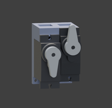
Assemble the side base to the main base.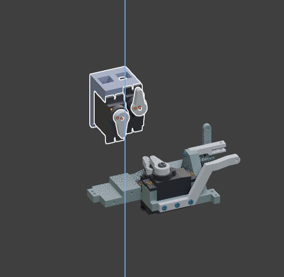
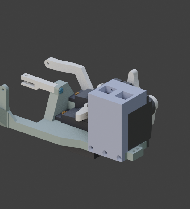
Use a 3 Self Tapping Countersunk Screws 2 x 6mm to maintain together the side base to the main base.Make sure they are fully seated in the countersunk hole, otherwise they might cause you trouble later once mounted in the head. 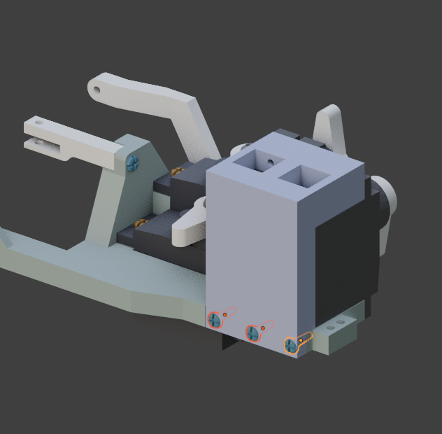
Use the 3mm screw supplied with the servo to fix both horns.
Use 4 Self Tapping Screws 3 x 10mm to fix the servos to the side base.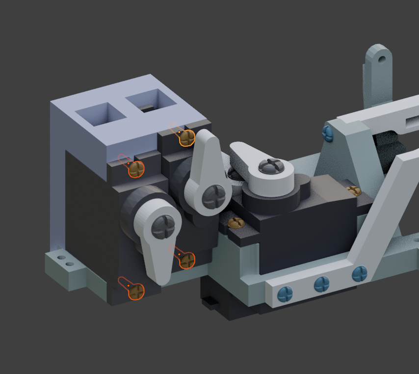
Add the hinge to the shaft. Respect the hole set up as shown. 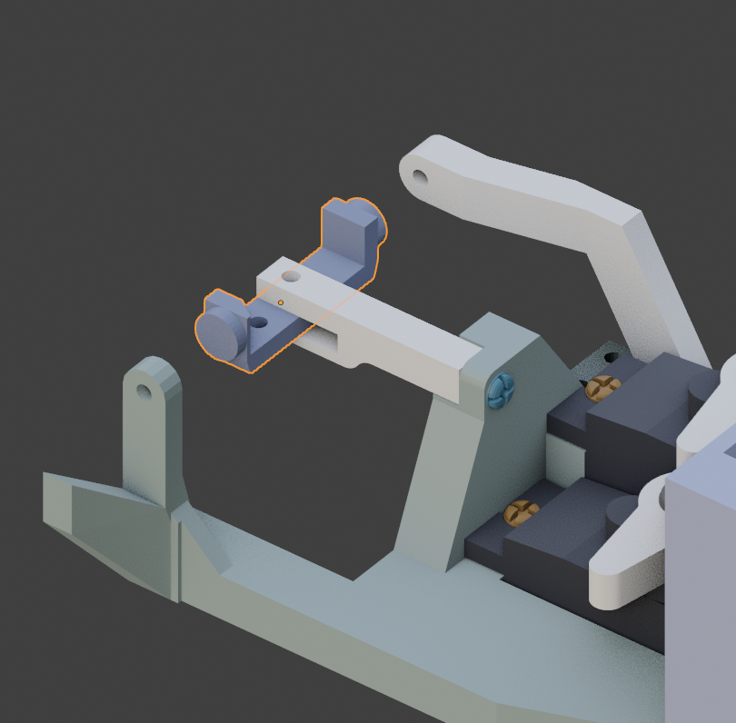
Use a 2 x 6mm Self Tapping screw to maintain the parts together. The hinge should be able rotate freely. 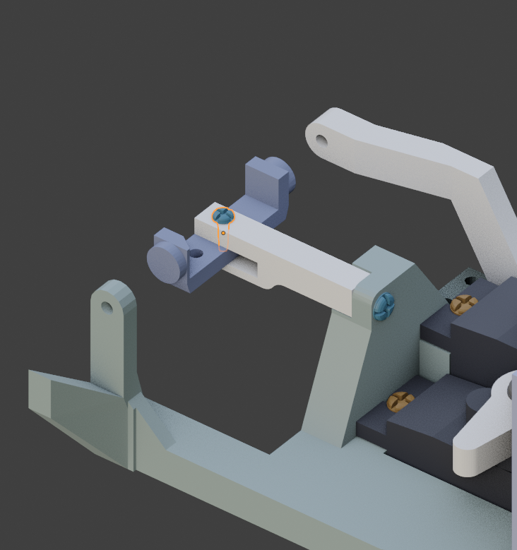
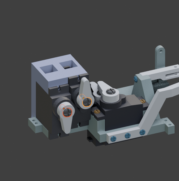
Get one of the servo shaft.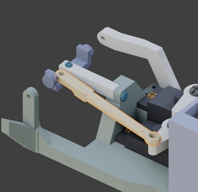
Use a 2 x 6mm Self Tapping screw. Do not over tight the screw, movement of the shaft should be able to rotate the hinge.
Get the second servo shaft and assemble with a 2 x 6mm Self Tapping Screw the tiny hinge.Do not over tight!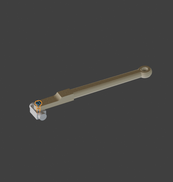
This is the position how we are going to set the shaft with the tiny hinge.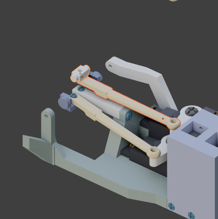
This is a bit delicate to do. You are going to clip on the eye socket. The eye socket is fragile,so be careful. Once assembled, it should all move freely, side ways and up and down. 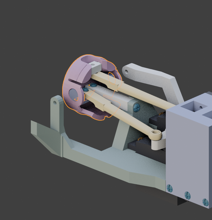
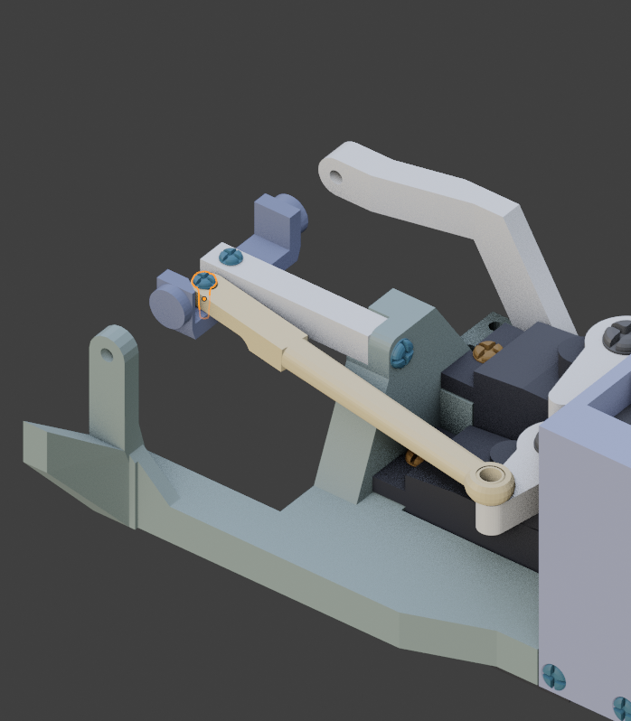
Now fix the two shafts with 2 x 6mm Self Tapping Screws .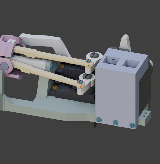
It’s time to add the camera. The camera black ribbon has to pass through the bottom hole of the eye socket.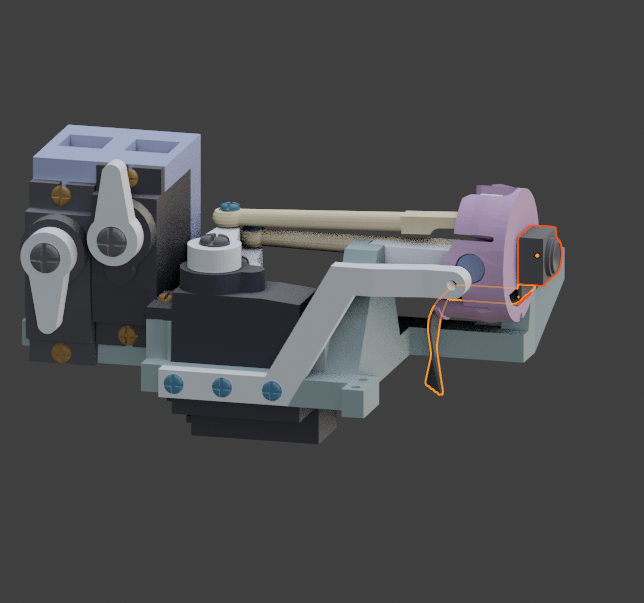
You can press the camera into the eye ball prior clipping the eye ball on the eye socket if it is easier for you.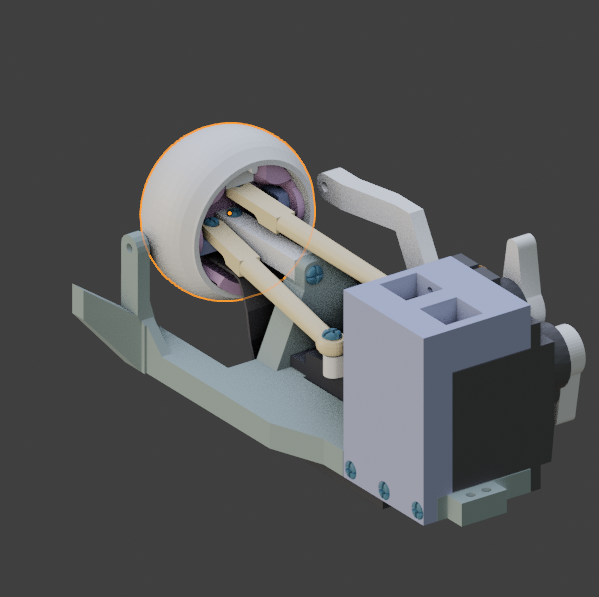
Cut and add the printed iris in the eyeball gap.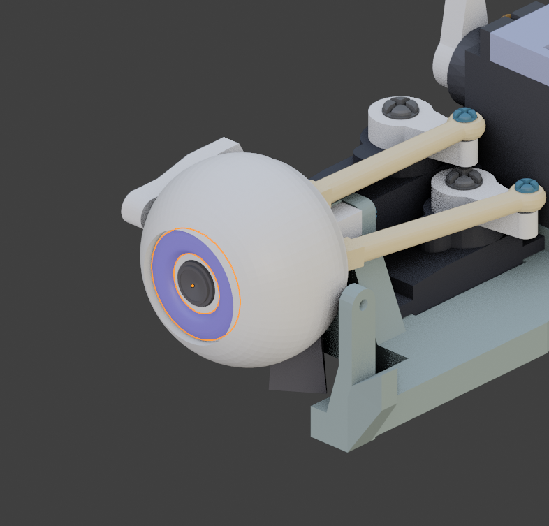
Add and glue carefully the transparent eye protection if you have made one.You can see in the old eye tutorial how to create your own.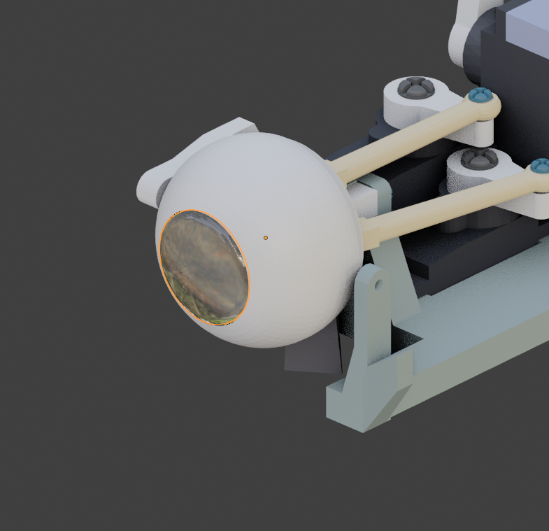
Add the lower eyelid.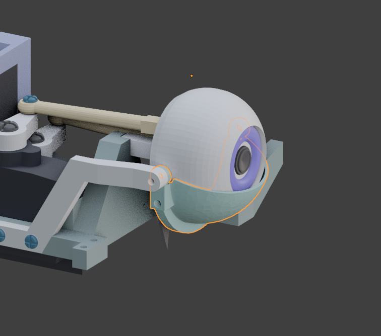
Use a 1.5 x 7mm Self Tapping Screws. Make sure your screw is not too long and too tight, it would avoid the eyeball to rotate freely.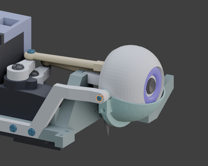
Add the upper eyelid.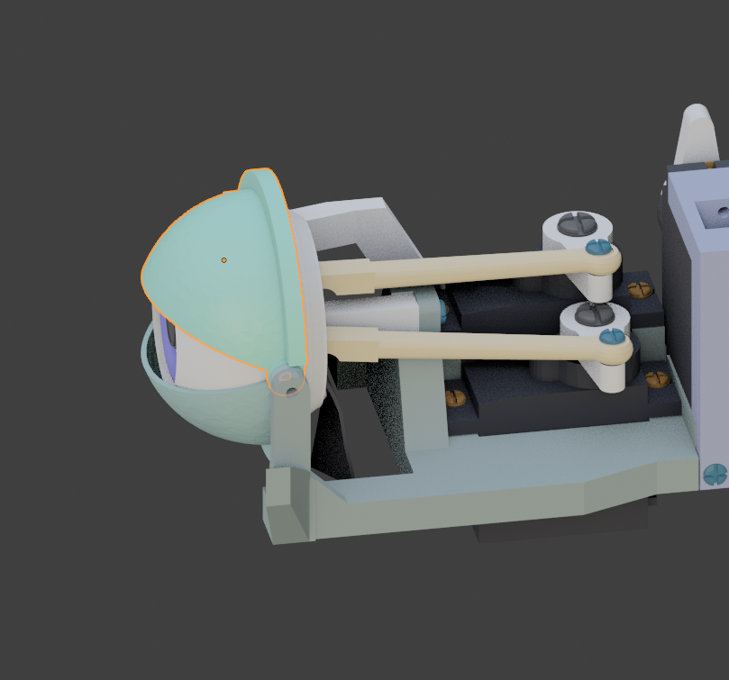
Use a 1.5 x 7mm Self Tapping Screws.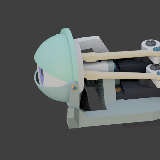
Add the two servo side shafts.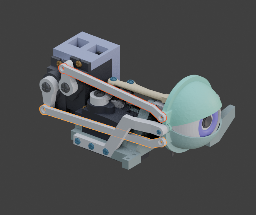
Use 2 x 6mm Self Tapping Screws. Do not over tight. 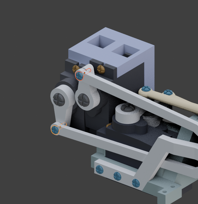
Use 1.5 x 7mm Self Tapping Screws to fix the shafts to the eyelids, do not overtight.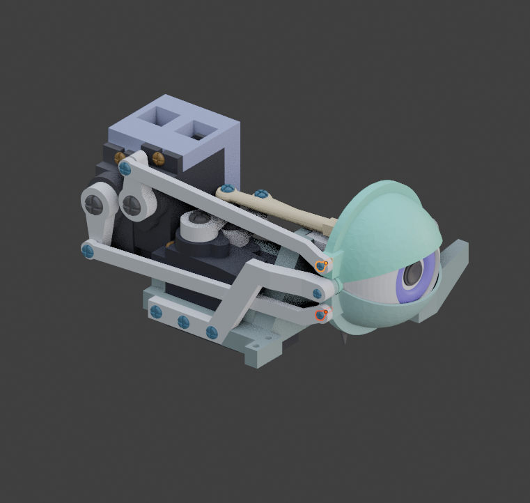
Connect the camera driver board and you are done with the right eye!!! You can now proceed to build the left eye following the same order.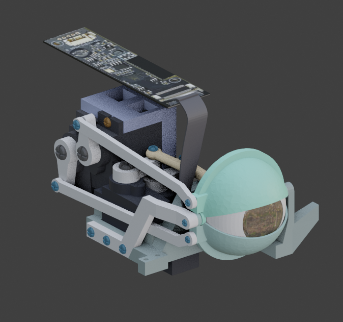
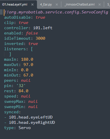
The i2Eyes are synchronized with the original eyes in Myrobotlab. This ensures that if the robot looks up, both eyes look up, same for looking down, right side or left side.
You can execute this script in the Myrobotlab python UI or edit your config located in data/config/yourConfig/i01.head.eyeX.yml and add in the synced section like below: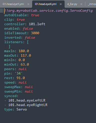
Do the same with data/config/yourConfig/i01.head.eyeY.yml: