Download STL files from the Gallery.
Before printing all the parts you should print the CALIBRATOR, to check if your parts will fit together. If you have a very hard time putting those parts together, adjusting the horizontal expansion setting of your slicer software can solve that, this setting can vary depending of your slicer and printer but users report to set it at -0.15 is a great place to start.
Important notice: I have created a new hand model called i2Hand. I recommend this new model, here is the link: https://inmoov.fr/inmoov-hand/
Original Hand model tutorial:
Here is the list of parts and the number of prints needed for 1 right hand and forarm:
- 1x Thumb
- 1x Index
- 1x Majeure
- 1x RingFinger
- 1x Auriculaire (Pinky)
- 1x Bolt_entretoise
- 1x Wristlarge
- 1x Wristsmall
- 1x topsurface
- 1x coverfinger
- 1x robcap3
- 1x robpart2
- 1x robpart3
- 1x robpart4
- 1x robpart5
- 1x ElbowShaftGear (if you built the bicep)
Here is the list of parts and the number of prints needed for 1 right wrist:
- 1x rotawrist2
- 1x rotawrist1
- 1x rotawrist3
- 1x WristGears
- 1x CableHolderWrist
Print wristarge, wristsmall, Thumb, with an infill of 30%, wall thickness 2mm, best with no support, no raft.
Print index3, majeure3, ringfinger3, auriculaire3, with an infill of 30%, wall thickness 1.5mm, best with no support, no raft, no brim.
Print robpart2, robpart3, robpart4, robpart5 with an infill of 30%, wall thickness 2mm, best with brim, no raft, no support.
Print coverfinger with an infill of 30%, wall thickness 2mm, with support. To get the best printing result on the covers is to print them standing up, instead laying them flat.
The wrist parts are good printed with an infill of 30%, wall thickness 2mm, with no raft, no brim, no support. The Gears of the wrist should be printed with the best quality your printer can give you.
Big bolts are now printable. (Strong enough for tests and even more!)
You can replace the 16x3mm for the fingers with pins/pegs of filament instead of bolts, it’s cheap, easy, and strong enough.
It was a suggestion of FreddyA.
- 1x8mmx8cm bolt to attach wristlarge to wristsmall.
- 1x8mmx4cm bolt to attach wriarge to thumbbottom.
- 1x8mmx6cm bolt for to attach wriarge to robpart1.
- 16x3mmx2cm bolts for all fingers hinges(I have recut each bolt to adapt to finger width)
These instructions are for the right hand. The left hand is similar but parts are mirrored.
Step1
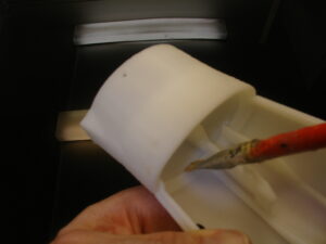
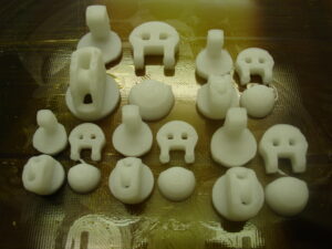
Remove the antiwarp supports and trim with a knife, RobPart2, 3, 4 and 5
Assemble together Robpart2 and Robpart5
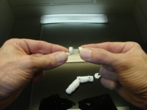
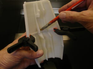
Help yourself with pliers to hold the parts together while you glue them with Acetone or Zap-A-Gap (ABS) or Epoxy 2 components or Zap-A-Gap(PLA)
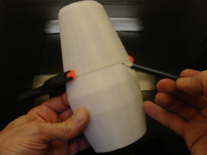
Avoid using glue on the outside other wise it won’t look clean. Control that your parts are correctly aligned.
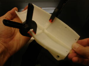
Do the same with Robpart3 and 4.
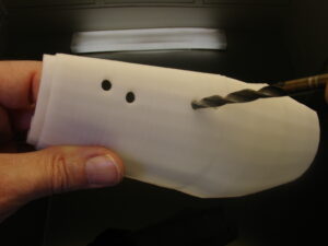
Redrill the holes on the side of Robpart2 with a 6mm drill(if you have a previous version with holes). These are for to fix an extra servo to get a double actuated thumb. See: http://www.thingiverse.com/thing:28124
Use the little rubber silentblocs that came with your servos(if you have the previous version).
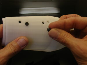
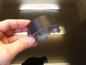
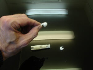
In Robpart5, insert two nuts for 3mm bolts in the printed cavities. Mine were not fitting, due to overhang, I heated them slightly with a lighter flame to make them fit.
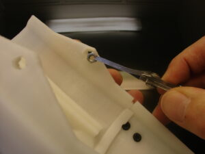
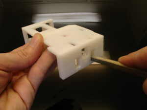
Trim/Fill the holes of the simple servo bed if there is overhang.
Set in Robpart5 the simple servo bed, make sure it is completely seated on the bottom.
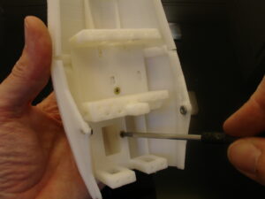
Glue or screw the simple servo bed with 2 wood screws.
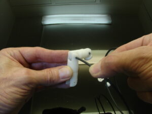
This is a new addon(Tensioner.stl) I designed in january 2015. The purpose is to keep constant tension on the tendons using a extension spring 0.5mm diameter, 1cm length(13/64″x13/16″). Use a small piece of tube to drive the tendon, this will avoid the erosion of the braided fishing line. I used SuperGlue to keep the piece of tube settled in the ring of the spring.
IMPORTANT: When setting tension for the tendons, the springs should stay at rest (not stretched out) other wise they won’t have the desired effect.
The springs are there only to give freedom to the length of the tendons when the wrist rotates.
So screw that addon on the simple servo bed and follow the next steps.
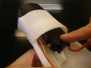
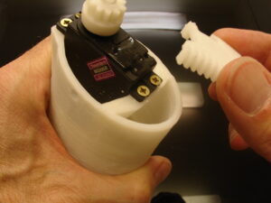
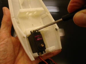
At this point we can mount the servos on simple servo bed.
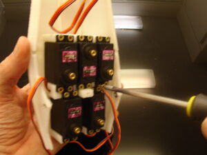
As you can see on my picture, I’m not using the HK15298 but some MG946r instead, for this tuto. The reason is that Hobbyking Europe is out of stock and I couldn’t wait.
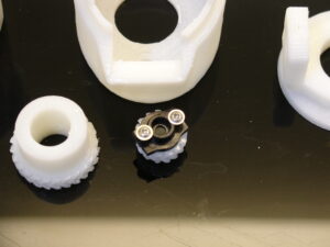
When you download my parts on Thingiverse, you can either choose to print RobRing or ServoPulley. It all depends, if you received with your servos the black actuator shown in my hand.
I personnaly use the ServoPulley. Redrill the holes with a 2mm drill.
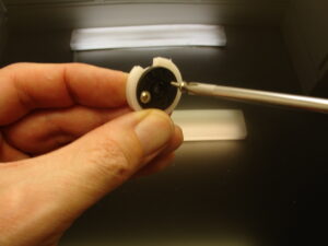
Use the screws that came with your servos to mount the black actuator.
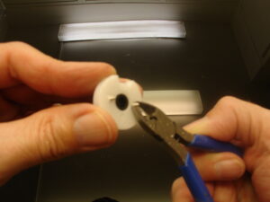
Cut the screws in the back with cutters.
Now use this script with your Arduino to set all your servos at 90 degrees. Set screw all the ServoPulleys in place as shown. Once the ServoPulleys are fixed, using the script again, set all the servos to Zero degrees. This will be for later when we attach the fishing lines. Avoid moving them during the next steps, otherwise you will need to reset them to Zero later.
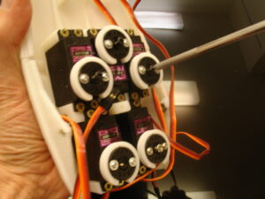
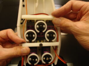
Mount on Simple servo Bed, RobCableFront and RobCableBack.
Step2
On RotaWrist1 remove the support.
Redrill if necessary the holes for the lining.
Make sure it fits on the Robparts.
You can use a fill to adapt it perfectly.
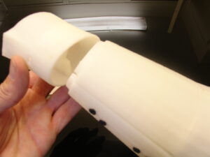
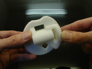
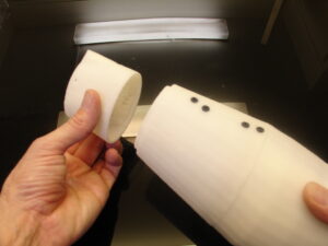
This is the correct way to mount it, see, Robpart2 and Robpart5 will be glued to RotaWrist1. I have seen many assembly where the wrist was mounted the opposite way. Notice the square part on RotaWritst, it should be aligned with the single hole of Robpart2 (4 black holes on previous model).
Glue RotaWrist1 to Robpart2. When doing this it is good to also set the Robpart3/4 cover to make sure the RotaWrist1 is correctly placed.
Insert your MG996 servo. Here we want a servo with 180 degree rotation. The HK15298 only rotates of 90 degrees.
Set the wood screws to fix your servo in place.
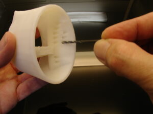
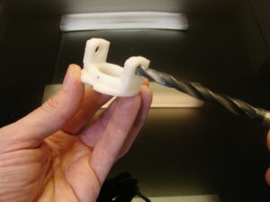
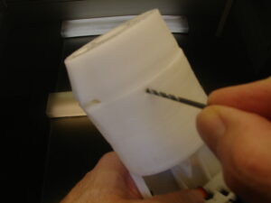
Redrill with a 2.5mm drill RotaWrist2.
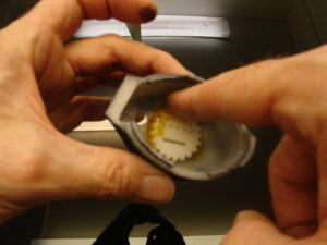
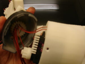
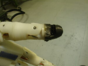
I like to spray paint in black RotaWrist2 because the grease used inside makes the part become yellow after some time.
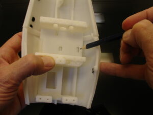
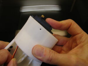
This picture is to show where to set the extra servo if you use the thumb with double actuation.
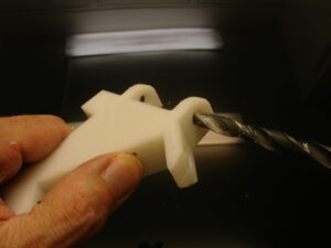
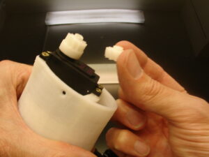
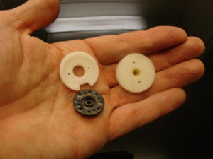
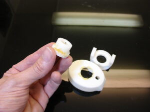
With your downloads there is two different small gears, use the one you think is most appropriate for your needs. Here is a previous tuto you might want to read.
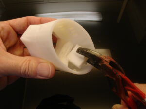
Use Epoxy two component glus to fix CableHolderWrist on the servo.
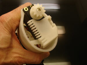
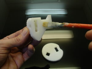
Use grease between the components. Using a white silicone grease will avoid showing a yellowish effect on the outside of your print.
Because I used yellow grease, I spray paint in black mat that part.
Mount RotaWrist3 to the big Gear.
Step3
See also this tutorial to create silicone finger tips.
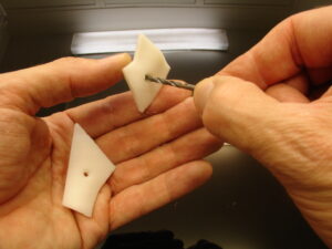
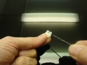
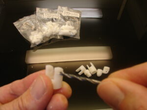
Time to redrill the finger hinges. I keep the fingers in seperate bags to avoid mixing them.
The outside hinge is redrilled with a 3mm drill.
The inside hinge is redrilled with a 3.2 or 3.5mm drill.
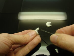
Fill the hinges to really adapt them the best.
Glue the parts together with Acetone(ABS)
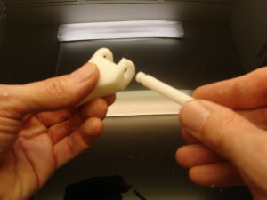
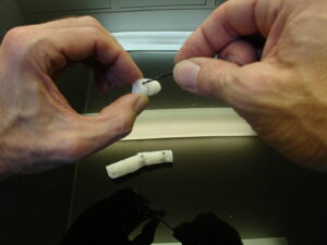
Use your 3mm filament to make pegs.
Cut with a knife the filament. If you don’t have 3mm filament you will need to do this with bolts of 3mm. I recommand the filament, it’s perfect, cheap and fast.
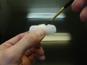
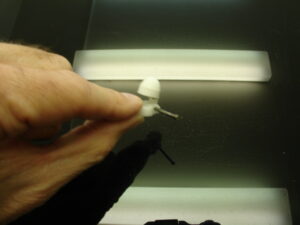
Redrill all holes of the covers with a 3mm drill.
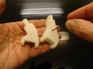
Redrill Wristmall and Wristlarge with a 2.5mm drill for to adapt the covers. If you don’t have exactly these size of screws, it doesn’t really matter. Use whatever you find at you hardware shop. Remember that the covers have a purpose and are necessary to have a correctly functional hand. They restrain Wristmall from going to the back of the hand. If you don’t understand read this.
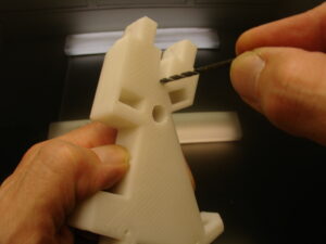
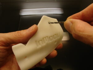
Redrill the hinges of Wristmall and Wristlarge with a 3.2 or 3.5mm drill
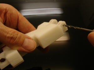
Redrill the big hinges with a 8mm drill.
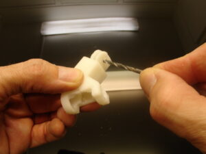
Ensure Bolts or printed Bolts run smoothly with no resistance but without wobbling.
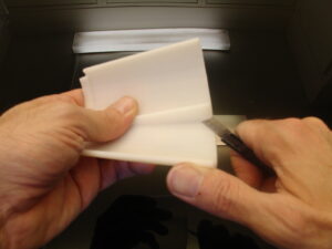
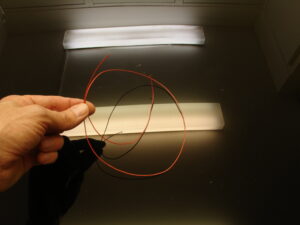
Cut 10 pieces of 75cm long of your braided fish line 200LB. Don’t use standard nylon because it stretchs.
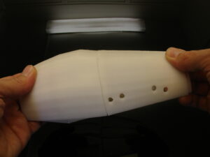
At this point it is good to decide if you want to have sensors on the tip of the fingers or not. You must have seen three holes above each other for the linings in WristLarge. The third hole (middle one) is for running electrical cables to wire up the sensors.
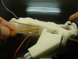
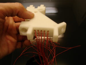
Insert the braided fish lines in the holes of Wristlarge. In this picture, I don’t have electrical wires for sensor fingers because it was a previous version.
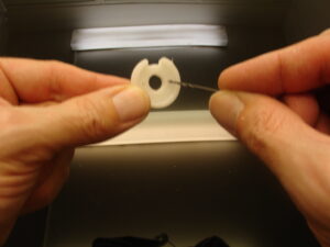
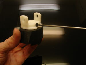
I have designed a little hole which can help you to guide the linings.
At this stage you might want to read this information: https://inmoov.fr/dilemna-with-wristsmallv3-part/
The electrical cables are running in the middle holes.
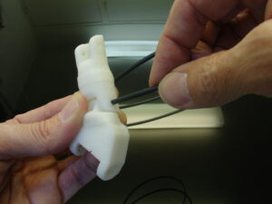
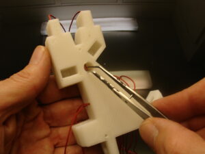
Run the linings into Wristmall. Make sure not to twist them on the way through. If you mix them up, the servos won’t be able actuate the fingers correctly.
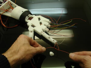
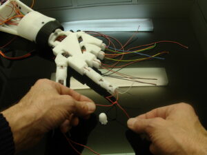
Repeat the wiring with the thumb. If you are using electrical cables don’t use the “Entretoise”, as shown above, otherwise you won’t be able to run the electric cables.
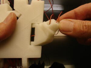
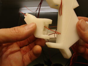
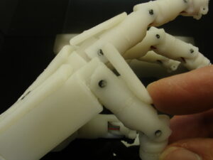
Line up the hand to the wrist.
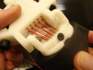
Now wire up the Wrist to the forarm, each lining has a slot.
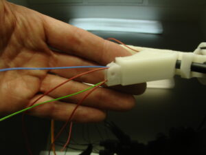
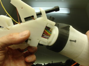
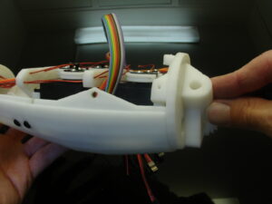
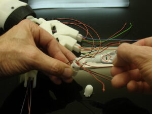
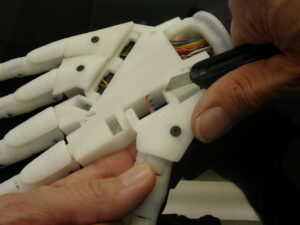
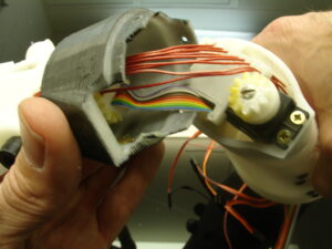
If you have electrical cable it will be like this. Using color ribbon is a good idea because you know what wire correspond to which finger and connection.
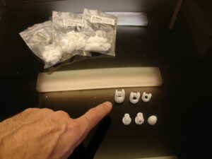
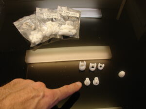
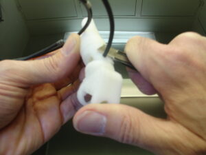
Add the “Entretoise” between the cables
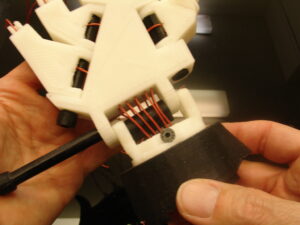
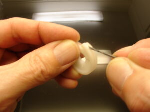
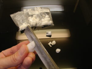
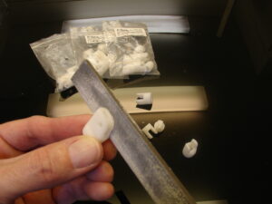
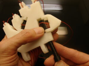
Use the “C” ring to end stop the bolt from coming out.
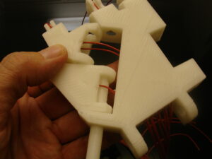
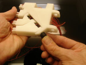
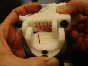
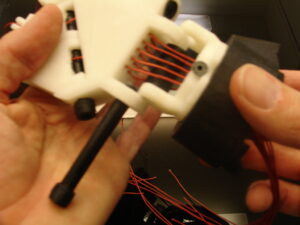
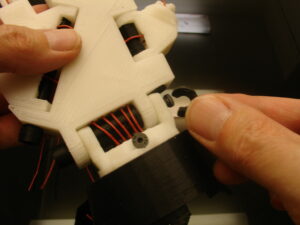
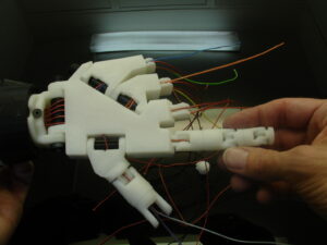
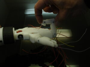
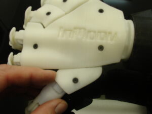
This is the back of the hand, you can see how I have set the cables. I’m not sure it is the best solution but, like you, I’m learning and discovering.
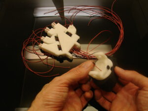
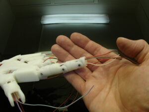
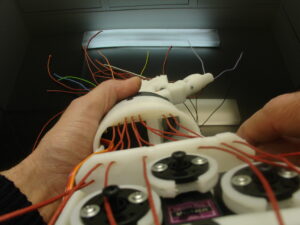
Here is how the lining should look up to the wrist.
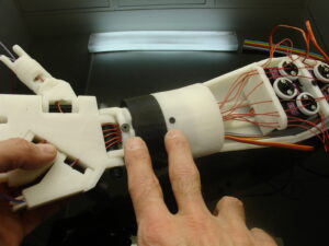
When you assemble the wrist make sure the servo is set at 90 degree and that the two screws on the picture are aligned. Until now I never did recomandation about this, and unfortunatly many of the gestures I created can’t be reproduced by other InMoov because the wrist isn’t set the same than mine.
Glue RobCap to ElbowShaftGear.
Aligning the squarry hole is the way to do it. If are using ABS and acetone, I can tell you there is no need to add screws if both of your surfaces are correctly flat.
Now glue this assembly to RobPart5, make sure it is correctly aligned in the slots.
Step 4
When assembling the fingers there is marks that can help you to see in which order it has to be done. I won’t go in those details here but you can find more instructions in the finger starter tutorial. The finger starter has numbers for an easy comprehension, the normal fingers don’t have those numbers, but the parts are the same.
Now that you have all your fingers assembled, for those that want to add sensors here is how we are going to proceed.
Finger sensor prints. Download them.
Glue the tip of the finger to the hinge tip. Make sure to align the nail lines, it will look better
Redrill the holes of the hinge with a 2mm drill.
Redrill the hole of the tip hinge with the same bit.
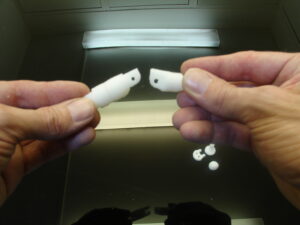
Add the hinge to the tip hinge and redrill them together to make sure they fit nicely.
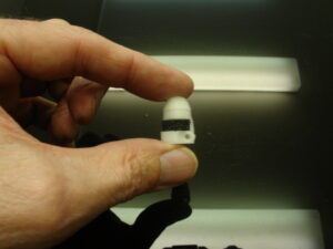
I used non flat metal nails instead of filament here, because the size of these parts are small. I just cut them at the size needed.
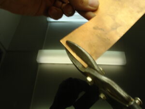
Cut some strips of copper of about 3 to 4mm large.
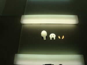
Recut those strips in tiny triangles. These are going to be contactors for the antistatic foam.
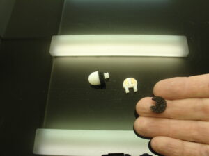
Cut with scissors some nice little rounds in your 4/5mm thick antistatic foam. This foam is sold with electronic components to avoid electric shocks. Most of the time we just throw it away when we buy components, you can also buy it in many electonic shops. It contains carbon which is an electrical conductor. When the foam is pressed against the 2 contactors, the carbon lets the current flow between them. More the foam is pressed and more current goes through. This is the info we will send to the Arduino Analog pins.
Glue with 2 components epoxy the foam to tip hinge part as shown on the picture.
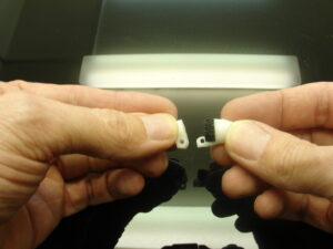
Try to assemble the two parts and see if it move. The hinge design is supposed to stop the hinge from opening further than the 5mm thickness of the foam.
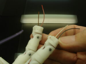
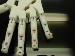
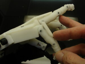
Time to mount the finger to Wristlarge. Notice the last hinge of the finger, this will receive the finger tip sensor assembly. All the holes in those finger parts should be cleared and large enough to have the 2 tension cables and the 2 electrical cables.
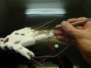
Run the tension cables and the electrical cables. One of each on the up side and one of each on the down side. Make sure to avoid any twisting of cables, this would cause to get unfunctional fingers.
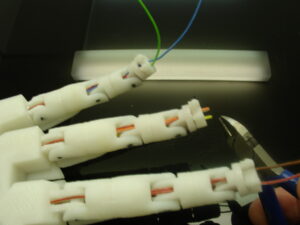
The color ribbon again is handy in this task.
Fold the fingers to smooth up a bit the cables in their path.
Make knots with the tension cables.
A bunch of them is necessary because we don’t want them to go through the holes when the servos are pulling hard on them.
What I do is even add glue to ensure any bad surprise. I also glue the electrical cables at the same time. When doing so, it is good to have the finger folded otherwise the electrical cables could later restrain the full motion of the finger.
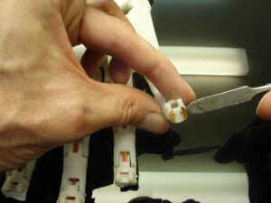
Cut the remains of the tension cables. Now glue the hinge of the finger tip to the last hinge of the finger. Notice the position, don’t glue them upside down. Remember I mentionned the tip hinge was design to avoid opening further than the thickness of the foam.
Cut each electrical wire at a 4/5mm length. Scary moment because too short would mean to redo all the wiring.
Cut and clear up the plastic on the electrical cable and solder the copper triangles.
Once done, fold the cable and lay the copper triangles in a flat position.
To maintain them flat during the time the glue gets hard, I used some tape, Look out for the tape you use as it maybe glued as well to the finger tips.
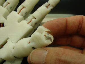
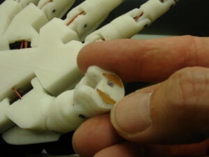
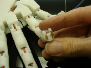
Now you can add the finger tip with the nail and you should have a sensor ready to be pressed and give feedback.
Glue the finger covers on the fingers.
These are used to avoid the finger going to much in a backward position and they also add a llok to the design
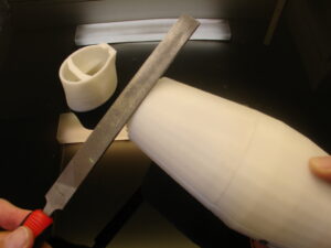
Do the same with the Thumb cover and Wristsmall. Actually I glue them first and then I add the screw, that keeps them well in place. Recut with a knife the two corners on the thumb hinge. If you don’t the hinge will be forcing against the hand cover.
Add the hand cover and check if the fingers are moving nicely.
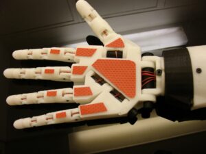
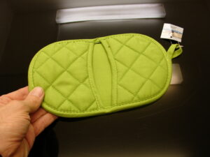
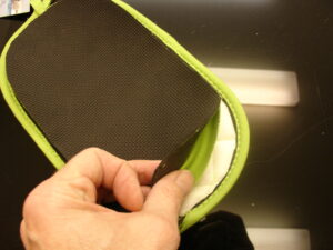
You can add Sugru on the finger tips or see this tuto, and ping pong surface in the palm of the hand for a better gripping. I found also some kitchen heat protectors for 1,50 euros with silicone surface. It is even better.
Hey it looks like you are set to tension the fishing braided lines!!
In the next tuto there is steps I’m going through again and they might also look a bit different. The reason is because of updates. Actually the next tuto was done before the tuto you just followed above.
You never used Arduino before, use this introduction.pdf or find more info on the Finger Starter tutorial
Go to this tutorial for tensioning the Linings.
Go to this tutorial to create your silicone finger tips.
Go to this tutorial to test the finger sensor.
Using MyRobotLab with a InMoov.minimalHand.py
OI…..queria saber onde conseguiu os arduínos e os motores para mover o dedos…também queria saber como se conecta o eletrodos no braço!!
Hi, can you translate in English? Thanks
Hi Gael, Vinicius wants to know where did you get the arduino components and the motors that move the fingers, and , also, how to conect the electrodes in the arm.
Hi, the Arduino for the arm and hand is a Arduino Uno, you can get it everywhere on the net (Adafruit for exemple), for the motors I use some HK15298 from Hobbyking.
The connection map is here
The connectors are here
HI i am making this arm but i dont know how to connect the leap motion to the arduino through my robot lab please help
You need a script that will do the relation between the Leap and the Arduino through MyRobotLab.
https://github.com/MyRobotLab/pyrobotlab/blob/master/home/hairygael/InMoov2LeapMotion1.py
Hopefully it still works with the recent versions of MRL.
Have fun!!
hi gael can i know how to strat my robot lab
Hello, Just follow the tutorial:
http://inmoov.fr/how-to-start-myrobotlab/
Hi Gael, I would like to know if my idea of a “Springmoov” is possible, where the servo holders are redesigned so they slide out easily, making room for a human arm to fit inside, allowing for manual control of Inmoov.
Hi,
I actually don’t know if it is possible.
I guess it could be possible, it all depends of your skills in 3D. Somehow you want to create a InMoov suit that you could endorse and manually actuate. Mainly the hardest part is to redesign each part to keep only the shell in order to create hollow pieces.
Have a greate built!
hello gael im little bit confused in connections pls help me i want to ask that in the hardware section a picture named Map connection V1 edited by “Peloche in which it shows that all fingers are connected to small nervo board which is furthered connected to the main nervo board and it also shows that all the servos are connected to small nervo boards then by ribbon cable to main nervo boad and also the 2 arduino mega were connected to main nervo board but you told that finger servos are directly connected to arduino uno which you showed in starter kit pls help me and also provide me full body connections
Hi, Gael
Awesome work! I’m going to print the parts and make one. But where should the Arduino Uno be settled in Inmoov’s hand? I didn’t find it in this tuto. Maybe u could give me some directions? Thank u.
BTW, for 3D print, are these 4 files enough for this tuto?
Hand_robot__InMoov
Adjustable_thumb_for_InMoov
Simple_Servo_Bed_for_InMoov
Inmoov_Robot_Rotation_Wrist
Thanks again! Hope I can finish it.
Yes this 4 files are enough. You can fit an Arduino Uno inside the forearm, there is space enough although it isn’t designed to do that. I had difficulties to get the USB cable inserted. If you want easy set up, go for Arduino Nano.
Hi, Gael
Nice work and I really want to make one. But I find out that it is really expensive to print these things (I mean hand) totally, since I have no 3d printer myself. I ask a company to print this, but need 18000 hkd, which is about 2400 us dollar. So I want to ask whether it needs such money? How much may this cost by yourself? It is too big number for me , since I’m steel student… I thought this may cost me about 200 us dollar. Or do you have any suggestion? Thank u very much!! Really love your work!
I am a collage student of Collage of Engineering, SCAU, CHN. I buy a 3D painter from TAOBAO.COM, It just cost me 1000 yuan(about 10 dollar), and I build the parts myself with PLA or ABS(about 3 dollar) buying from TAOBAO.COM too.
3D printer, not 3D painter…… Sorry for the mistake
No problem.

Hello,
13 dollar printer? That is unbeatable! (I think there must be an error with your rate conversion)
Thanks for the info.
1000yuan = 10 dollar ? excuse me ?
I’m still student not steel student… Sorry for the mistake in last comment.
No problem
Hi, Gael. So the question about the budget? How much will it take for the 3d print of this part? I mean the hand and forarm. I may have no enough money for it. Any suggestion? Thank you
Hi, it is hard for me to say because it all depends on your material and printer experience. I would say that with 15 to 20 euros of ABS it is largely enough to print those parts. If I remember correctly, the hand and forearm have a total weight of 750Gr. But you need to have a 3D printer.
Thanks! But I have no 3d printer right now, and it is really expensive to print by company outside, about 1000 euros or even more. So will you sell these parts? Maybe estimate the price first and then I could buy these 3d print components from u. I don’t know whether this is possible? Anyway, thanks for reply and I really appreciate your work.
The process of 3D printing isn’t very expensive in material cost but it is excessively time consuming. This will improve rapidly, I’m sure. It is the reason why printing companies have high rated prices. I don’t print parts for builders because I would just spend my time doing that, and I rather keep working on the project instead. What I suggest, you can either find a somebody with a 3D printer in your area and do somekind of exchange of help or you buy yourself a second hand small 3D printer for about 300 euros, which will be usable for your future various other projects.
Okay, thanks!
Firstly I wanted to thank you for this extraordinary project open source robot to make in 3d printing … Many Thanks!!!
I start printing my first pieces of hand inmoov and it went well …
However I have three small questions:
First: About Electrical wire : what type of wire I should buy and how long of wire to put all the robot (wire tape or twisted ribbon)? (Maybe the electric wire supplied with the servos enough?)
Second: Do you know if it would be possible to connect the robot inmoov to database cloud RoboEarth (the worlwide web for robot) to connect all inmoov robots all owners to learn from them even faster?
Third: Is there a forum Inmoov in French language?
Hello, Gael. Thank you for detailed explanation! I’m very impressed by your project.
I just would like to ask a short question: have you tried to drive the hand, feeding the arduino from computer’s USB hub? Do you know approximate maximum value of current which passes?
I feel like I’m asking a stupid question. But every time I write to servo some angle, the voltage falls and board reboots. I though USB hub is able to provide enough current, but it seems to not. Am I write or I should re-check the way I’m connecting the servo? It’s MG946 and it seems to have the same contacts as HK…
Merci beaucoup, Gael!
It seems you are powering all servos through your USB, which cause the Arduino board to reset.
The Arduino board can only power up one servo. If you power more servos, you need to have an external power supply. See how to:
http://www.inmoov.fr/default-hardware-map/
Don’t forget to ground your Arduino board to the external power supply.
Bonjour Gael,
Thank you for your answer! You’re right, of course, I need external power.
Could I ask another question, please? This is about the MG946 control. In main loop I do something like this:
for (pos = 0; pos < 100; pos +=1){
servothumb.write(pos);
delay(100);
}
And then I do the same thing, but in opposite direction.
But instead of slow turning and then returning the servo goes to the extreme position and stucks there, producing noise and taking large current. Maybe there is some special code I need to add to your Arduino sketch for servos to control MG946 instead of HK..? Could you give me an advice, please?
Thank you very much for your help!
Scripts will work the same for the HK15298B as for the MG946R.
Which script are you using? Is it a script I posted? Can you send the link?
If you need more help about scripting you might want to head over to Myrobotlab, the members are more into programming than me.
Yes, at the beginning I used a file which was on the site on May. Now it isn’t (or I just can’t find it). May be this file is a new version of it:
http://www.inmoov.fr/wp-content/uploads/2013/10/Arduino-Schetch-servo-zerorestmax.txt
OK, I will look for it on MyRobotLab forum. Thank you for the advice.
How powerfull should the servos be?
Hi there is the BOM here:
http://www.inmoov.fr/default-hardware-map/
12kg torque should be the minimum, because there is force lost when fingers are folding.
I got the FS5106B servos they are 5kg at 4.8 and 6kg at 6, will those not work?
Hi, you need to check the specs size yourself as i don’t have time to compare all servo possibilities. Let us know on the forum if they fit, others might be interested.
I have created the Hand and Forearm of this Inmoov collection. I have a DC power supply connected to the Arduino to provide power to all servos (set on 6v), and the voltage from the Arduino itself powers the flex sensors. All works well, other than if multiple flex sensors are flexed. This causes multiple servos to move (e.g. 3 Servos from 3 Flexed Sensors); when this happens, the system stops working and bugs out. I think it is due to the drawn current from the multiple servos acting at the same time. Would you know anything on this to prevent it? I am very stuck.
Any help would be appreciated, thank you.
Are your servos correctly grounded to the Arduino, same question for the flex sensors as shown on the bellow sketch?
http://www.inmoov.fr/wp-content/uploads/2013/12/Circuit1Arduino.jpg
When servo power supply isn’t grounded to the arduino ground, it always causes the servos to act strangely, this could be your problem.
Hi, Gael
Awesome work! I’m already print the parts and make one. But where should i get the Arduino Uno connection tutorial? and are use the motor servo driver or not? I didn’t find it in this tuto. Maybe u could give me some directions? Thank u.
You should find all these information on the finger starter tutorial.
http://www.inmoov.fr/finger-starter/
Hi Gael, what size of screw do you use for the hand cover? Thanks!
Hi,
I actually used 3mm diameter screws, the length vary following the different places.
Hi,
could you tell me if the HK15298 really works with this tuto ?
I found this document : http://inmoov.fr/simpler-servo-bed/
but is it still relevant ?
Thx
Eyton
The HK15298 or HK15298B work with the simple servo bed which you can find in this tutorial:
http://inmoov.fr/hand-and-forarm/
The simple servo bed STL files are here:
http://inmoov.fr/inmoov-stl-parts-viewer/?bodyparts=Forearm-and-Servo-Bed
I think this answers your question.
Hello Gael,
Do I need the simple servo bed if I am using MG946R Servo motors?
If yes, where do I find the STL file for the simple servo bed?
Hello,
Yes you need the servo bed if using MG946R servo.
You can find all stl in the gallery library:
http://inmoov.fr/inmoov-stl-parts-viewer/?bodyparts=Forearm-and-Servo-Bed
Yes thank you Gaël.
However I have a problem mounting HK15298 in the RobServoBed.
Here an illustration :
https://framapic.org/r2sG9ANsXuWI/yG2c7iuo
Here the modified part (work in progress) :
http://www.thingiverse.com/thing:1036300
Yes there is a gap between the servo bed and the HK15298, that is if you want to use the rubber rings to reduce vibrations. The gap doesn’t affect the strength anyway.
rubber rings supplied with servos ?
Yes the rubber rings that come with servos.
ok thank you !
now I’m on the antistatic foam and I would like to know if there is a way to be sure that foam is the good one, maybe by testing it with a multimeter set in continuity test mode ?
If you test the foam with a multimeter it should let the current pass through.
Yeah definitely with a multimeter.
What is the price of 3d right hand…
Plz tell me hurry…
Hello Gael,
“… using a extension spring 0.5mm diameter, 1cm length(13/64″x13/16″)”
Do you confirm this ? 0,5 mm ?
And second question : Do you have a picture of the connection between the spring and the tendon ? I don’t understand this part…
Thanks for answer
My bad it is 0.5cm diameter, 1cm length.
I can’t make a picture at the moment because the hand with this set up is in Los Angeles for a Discovery Chanel film…
Hey Gael, or anyone else that could answer,
Is 0.5cm the wire diameter or the outer diameter for the springs? Would it be possible for someone to post a purchase link to an appropriate spring? I’ve had a terrible time trying to find the correct size in the States.
Here is on the forum a thread regarding the same question:
https://groups.google.com/forum/#!msg/inmoov/MEK-yS-DI80/dJY_MQunAgAJ;context-place=forum/inmoov
D’oh! I should have checked there first.
Thanks Gael!
Great Job !
I’m printing now and have almoust the arm and hand.
But i have problems to print the cover of the hand.
I printed like te stl file position.
I get spaces in the top survase .
I print it with 30% infill no support.
W
Can you tell me what i do wrong?
Sorry for my bad english.
Leo Garstman
Hi,
You need to set your slicer to have 3 shells with 30% infill. A shell is outer line of your print. The three shells correspond to three times the resolution of your extrusion.
So I suspect, you have currently only one shell.
Hello Gael,
I have to say this is an amazing design and I am currently printing the right hand for my EPQ project at college.
I was just wondering how you stop the print from warping because when I was printing the palm-part yesterday and the edges started to warp a quarter of the way into the print so i had to stop it .
Hello, I’m glad you enjoy the project.
Warping is a very common issue related to many variables. Heat, air, material, printing surface…
I would suggest heading to the InMoov forum, make a search with keyword “warp”, “warping”. If you don’t find your answers, post your question there, many people enjoy explaining stuff about 3D printing issues.
Hello,
Thanks for that Gael, I will post it on the forum later today.
I was just wondering if it matters what the diameter of the fishing line is.
and does it have to be braided and 200lb
Thanks is advance,
Deeta Pallent
Another thing I wanted to ask was did you use screws to put the fingers together or did you print pegs to put it together.
Thanks again,
Deeta
Hi Gael,
I’m assembling my first hand/arm arm and have a couple of questions. First, There isn’t really a location for the Arduino in the arm, correct? I printed the little Arduino tray but I don’t see anything indicating it should go inside anywhere or how to route the servo wires. Should they just be run through the larger hole in Robcap and then directly into the Arduino?
Next question. I plan on building the bicep and shoulder, but the entire planet is out of HS805BB servos at the moment. The TS-80 looks like a decent equivalent. Have you heard of any issues with it?
Next question. Have you tried and do you approve of the little dual-track servo pulley creations available on Thingiverse? It seems like a simple solution to the back-side slack me, but I thought I’d ask before hooking them up.
Last question. The Nervo board system looks awesome! Are you running all of the power to run the servos through the ribbon cables or is there a separate power lead? I’ve used servo-to-cat-5 adapters in the past but have always had to run a separate lead for power. Just trying to figure out how it works before I invest in a set.
Keep up the terrific work!
Thanks,
Scott Hodges
Hello Scott,
-Indeed there is no specific space for the Arduino Uno tray. Actually the Uno trays remains in the downloads mostly for people who want to only built tha hand and forarm.
If you plan to build the robot, I suggest using 2 Arduino Mega. There is trays available for the Mega as well on my site(??) I need to check if I did add them in the recent website…
-I haven’t got any bad feedback about the TS-80, but nothing that ensures the fact it fits correctly. I think most people have been able to get HS805BB until now.
Before I started InMoov, the HS805BB was available everywhere and for a very reasonable price. With the increqse of purchase of HS805BB, the prices went up and they became rare.
-I didn’t try the dual channel servo pulley, but I’m pretty sure it is a good option. Test it on one and give us feedback, I would be interested to know.
-The Nervo Board powers the servos through the 14 cable ribbon. 3 cables are dedicated for Vc+ and 3 are dedicated Gnd, the rest are for the PWM pins.
Remember you will need a heavy Amp power supply if you don’t choose to use the 6V12Ah battery. For the whole robot you will need around at least 20 Amps. The more is better.
Hi Gael,
Thank you for the prompt and courteous response. I’ve got a couple of questions at the end.
I do have a couple of Arduino Megas but they are deep inside some Halloween animatronics at the moment. I probably have 6 or 7 spare Unos, so I’m using them for now. It looks like there may be room for an Uno or nano in the bicep structure, but I’ll need to finish printing and assembling that to figure it out.
I do have two item that I think you might want to recommend to people who plan to just build an arms. The first is a sensor shield for the Arduino. It has pin-outs for servos and even stepper motors. It eliminates the need for a proto-board and wiring, and allows you to run a separate PS right into the board. I think I paid $4.00 each for a couple of them on eBay. Just look up “Arduino sensor shield” there. Drop it onto an Uno and the pin-out puzzle is solved.
The other thing I recommend is an S-200-5 single bus power supply to run the servos. This thing looks just like most 3d printer power supplies and some include a fan. I used to use PC power supplies to run my animatronics but they have limitations on the amperage on a single bus and I would constantly blow them out. 5v might be a little low, but there is a pot that will let you dial it up a little. The one I have is rated at 5v and 40 amps.
Oh, and I am trying the dual track pulleys. There is a very slight clearance issue with the center reversed servo, but I’ll work that out.
OK, lots of talk, finally a question. I loaded the little centering sketch but have not yet run it. (I should have run it on the wrist servo BEFORE I installed it…. Anyway, here is the question. Which rotation is close fingers and which rotation is open? Clockwise? I see the numbers in the sketch but am having a brain cramp. “All to rest”, (0 degrees) would be open hand? All to max would be closed hand and 180 degrees clockwise, right? And all to 90 would be a cupped hand? I’m using these beta-pulleys, so I’ll have to figure out limits myself, but does it generally require all 180 degrees to get from open to close on all fingers? A little clarity there would probably save an hour of messing around.
I’ll post some pictures over on Google when I get the pulleys working correctly.
Thanks a bunch.
Scott
Hello Hodge,
You want to look over for the Nervo Board which is a Arduino shield dedicated to InMoov if you want to move the whole robot.
Of course any shield can do the job, but it solves a lot of pain figuring the pinout. The shield you mention is a very good price for someone who wants onty to actuate a hand!.
I recommend powering the servos to 6V instead of 5V, it makes a big speed difference when InMoov is moving around his arms.
There is a power supply I have been using for almost two years on InMoov that does pretty well the job for now. But it is almost not enough anymore. It has a range between 5.5V to 15V at 20Amps. It is discribed in the BOM.
Batteries are actually the best specially when InMoov is moving around. The 6V12Ah are very cheap and do a good job for at least 35 to 45 minutes depending on what you do.
All to rest, (0 degrees), is indeed a open hand.
And all to 90 is a cupped hand.
All to max is closed hand at 180. This varies a lot depending on the servo you use, the pulley you use, and how you did the tension.
Adjust each servo and map them in MyRobotLab when you make your own script.
Thanks a lot for your work Gael!
By the way! want to use a battery car to move InMoov??
http://www.ebay.com/itm/WaterProof-DC-12V-24V-to-6V-30A-180W-STEP-DOWN-Power-Converter-Regulator-/291279219075
Even underwater!! XP
Gael, Thank you for all the great design and information.
Question- When the wrist turns the fingers do not operate as well (do not fully open or close) as they do when the wrist is not turned. How can I compensate for the wrist turning in tightening the tendons?
There isn’t really a solution to compensate. When the wrist turns, it also pulls slightly the tendons, therefore it acts on the fingers. I don’t know if you have used the spring tensioner which helps somehow.
Thank you. Yes the tensioner does help.
Hello Gael,
This is amazing project !
It feels that I am creating somebody pieces by pieces.
I have a questions concerning the setup of the poulies in to the servos to control the finger and wrist.
Shall i run this program with 90 instead of 0 then place the poulies then put back 0 ?
void alltorest() {
servothumb.write(0);
servoindex.write(0);
servomajeure.write(0);
servoringfinger.write(0);
servopinky.write(0);
servowrist.write(0);
servobiceps.write(0);
servorotate.write(90); //Never less then (20 degree)
servoshoulder.write(30); //Never less then (30 degree)
servoomoplat.write(10); //Never less then (10 degree)
servoneck.write(90);
servorothead.write(90);
}
I am confused in the step:
Now use this script with your Arduino to set all your servos at 90 degrees. Set screw all the ServoPulleys in place as shown. Once the ServoPulleys are fixed, using the script again, set all the servos to Zero degrees. This will be for later when we attach the fishing lines. Avoid moving them during the next steps, otherwise you will need to reset them to Zero later.
Thank you again !
Hello Dominique,
Set your servos to zero to have the fingers spread flat. When the pulley rotates to 90 it then close the hand or finger. MyRobotLab has a mapping control which allows you to define and adjust precisely the movement in order to avoid over pulling on the tendons.
Hi there!
My HK15298B’s had just arrived!
I know they only spin 90º…but when I gave order servo.write(25); and servo.write(155); it does spin from one top to another.
I would love to know if is normal for the servo to not spin from 0ºto20º and from 160º to 180º.
Also seems motor controller does some kind of mapping of angles as over those 120º it really makes a 90º spin.
Hope is everything ok.
Thanks again Gael!
Hello Pablo,
The mapping is done by MyRobotlab. If you only use the Arduino sketch, there is no mapping but it does look like a mapping effect.
Therefore you can write servo.write(0); and servo.write(180) and it will do the full 90 degree movement.
Hi!
About the tensioner: Once i mount RobCableFront to the servo bed there is not enough space between RobCableFront and the part of robpart2 (v3) where the servo for the thumb with double actuation is fitted. When the 2 walls touch about 2-3 mm are still needed. Maybe I missed a corresponding new part or I’m wrong with how I think the tensioner should be mounted. Of course I could just shrink it a bit.
I didn’t take in account the servo for the double thumb actuation… Do you have an extra servo placed? Is that why it doesn’t fit?
Actually I have not installed any servos yet, only the printed parts. I’ve made some photos. Again maybe I’m just doing it wrong.
my link didn’t work h**ps://cloud.klauswagner.com/index.php/s/jVWrnYZWLsxDqPO
I have fumble on the same problem. The extra servo is not the problem, but the plastic part holding the extra servo. I don’t see how the hole there are use, maybe it was to hold the first version of the servo bed? If so, I think that part can be cut to make place to the tensioner.
Gael, can you confirm this?
i am making inmoov right hand so can i get the Tensioner.stl file for it please i am not getting it anywhere can you please provide me the link of it
Hi,
I have couple of questions regarding the hand build.
1. I am using a MG996R for the wrist rotation and I was wondering if you are referring in to center position(90) of 0-180 servo as 90deg or the 180 position as 90deg in this tutorial. I asking because due the gear ratio used we get only a total of 90degress of rotation. If I set center position as 90, I get 45deg movement in either direction compared to 90deg to & fro motion when setting it to 180 position.
2. I am having trouble with finger tension along with wrist rotation. If I turn the wrist the line tension is high and affects finger movement and the line may snap. But if I try to keep the line loose to enable the wrist to rotate, the finger movement is not correct due to slack in the line. I am also using springs like its mentioned in the tutorial but problem persists. Is there any way to achieve both – good finger tension and wrist rotation?
Thanks,
Prasad
Hello, I am indeed refering to center position(90) of 0-180 servo as 90deg. As you came to realize by yourself, adding more rotation to the wrist would increase the issue of non tensionned and over tensionned fingers with full wrist rotation.
The spring tensioner solves that issue pretty well in my case. When setting tension for the tendons, the springs should stay at rest (not stretched out) other wise they won’t have the desired effect.
The springs are there to give freedom to the length of the tendons when the wrist rotates.
I hope its clear enough…
Thanks Gael for the info. This helps me complete this forearm build and move on to fix the other arm.
I need to know how to connect the 6 servo motors power source someone has a tutorial? I’m using the servo motors MG946R and nano arduino
Hi,
Look at the Hardware map in “Build Yours”.
Hey Gael!!
A question, im a bit lost! The lines are setted up on 0 degrees? Can i set them like that mooving them clockwise? In the pictures the actuators are set up while the servos are on 0 degrees? Thank you!!
Hi Gael. Nice to meet you.
I am Paul in Korean
I wonder why scale of Robpart3,4 and Robpart2,5 are diffrent.
when I use a 3D printer, I don’t change the scale of robparts but it is printed differently for size.
I want to send you picture of my printed part. So could you tell me your e-mail address ?
if you can solve my problem, just post comment.
Thank you.
Did you download my original parts on InMoov.fr , or on another website?
You can post your picture by creating a topic on InMoov forum, others might also be able to help you.
Hi.
I printed all parts and no resizing is needed. Something strange.
Try to open those into some OpenCAD, verify the size of parts (for sure that is the original size). Than to to printer software, load model and check those exterior size. It can be your printer auto resize it to fit the bed (improbable, but is the only possible explanation).
Hi Gael
Is there a detailed description of how to mount the tensioner? I have printed TensionerRightV1.stl and would like to screw it to the servo bed but just can’t see from the picture where exactly I have to put it. Do I have to screw it through the small hole on the servo bed above the opening that looks like a small house?
Daniel
Attachment of the tensioner to the servo bed should be done via the main screw, but it is necessary to also add some glue to make sure it does not rotate on the screw.
Servo bed and the tensioner were designed at different time, that explain why the attachment is not self explanatory.
Thanks for your reply Gael. But somehow I still don’t get it and I am starting to wonder if I printed the correct tensioner.
With the tensioner, do I still need RobCalbeFrontV3?
Then how do I mount this if the tensioner is already mounted?
Please see this picture of my prints for illustration: https://dl.dropboxusercontent.com/u/70755681/Tensioner.jpg
Hello,
Sorry for the delay, I am very busy at the moment. The RobCableFront comes between the tensioner and the RobServoBed.
http://inmoov.fr/wp-content/uploads/2013/09/InMoovTensioner2.jpeg
Hi Gael!
I’m a student at University of California, San Diego and we are working with faculty adviser to build a functional prosthesis for a boy and we want to build a human hand first to do our testing. My question about the InMoov hand is that, what was the goal and philosophy behind your design? For example, did you look to simulate the movement and joints of a human hand or was there a specific functional purpose?
Thank you!
Doris
Hi Doris,
Initialy I designed the prosthetic hand for a commercial campaign in 2011. Because the job didn’t happen, I designed it to look the best way but still behing mechanicaly simple looking and mainly easy to 3D print for everyone. I wanted the joints to be rather accurate situated compared to a human hand. Before releasing the files on the Internet in January 2012, I modified them to add motors and mainly to have independant finger motion using an innovative technic of double actuation through the servo rotation. The philosophy was to create a simple product, easy to 3D print without support, for anyone that was in need to have prosthetic hand.
Can someone help me understand at which position should the right wrist servo should be when is attached to the forearm? In the middle of movement? So it moves for both sides or is it already at max ? And only moves towards inside? Thanks in advance
Hello Pedro, when the wrist is flat as in this picture your servo is at 90 degree. (considering it can potentiolly rotate from 0 to 180)
thanks!!!
thanks Gael!!
Sorry for keep asking, does that mean wrist will moove 90 degrees from there to one or the other direction? or it will only moove for one?
Thanks in advance
what makes me confuse is that in MRL it will be in the middle of the button bar right!?
Salut gael, je voulais savoir si 6 servos MG946R pouvait marcher pour la main droite et l avant bras. Je me demandai aussi ou trouver les connecteurs serveurs-arduino Uno.
Merci d avance.
Alexandre
Tout dépends de ce que vous ferez avec ce bras. Les MG946R peuvent fonctionner correctement mais dans une certaine limite d’utilisation. Il y a beaucoup de perte de couple tout au long du tendon, lié au frottements divers. Avec les HK15298b la main peut fonctionner toute la journée sans risque de bruler un servo, il ne faut pas envisager cela avec les MG946R.
Les connections sur l’Arduino se font grace à la Nervo Board, qui peut être montée sur une carte Uno ou une Mega, suivant ce que vous souhaitez réaliser. Le montage sur une Uno, nécessite de découper la Nervo Board (voir tutoriel)
Hello Everybody.
I am completing my first arm+bicep. I found that instead of using a plain Arduino there is a new absolutely great board for 12 euro “SunFounder PCA9685 16 Channel 12 Bit PWM Servo Driver for Arduino”. It is a clone of Adafruit’s same board (25 euro).
It can control up to 16 servos, enough for all Arm servos.
It has a form-factor of Arduino Nano and can fit into the forearm directly. So the entire wiring from the Arm would be 5 wires only (VCC, V+, GND, SCL, SDA.
I have tested it and it works with big motors MG995 Tower Pro (13 kg/sm).
You can find it on Amazon, with the Prime delivery I got it in 2 days.
http://www.amazon.de/SunFounder-PCA9685-Channel-Arduino-Raspberry/dp/B014KTSMLA?ie=UTF8&ref_=pe_386171_134044401_TE_dp_1
Regards, Vasily.
Vienna, Austria
Hello Vasily,
Thanks for the link and information!
I had bought three years ago some 16 channel PWM boards from Adafruit to drive all the fingers and the arms but according to Greg (MyRobotLab Creator) we wouldn’t be able to handle the speed and ramping of each servos using those boards. I think there has been some progress recently done about that and some of the MRL developpers might give you better information about this.
Gael…if no one has said this…THANK YOU…you have developed the coolest project on planet Earth…You are so humble and this has taking you years of work…Thank You
Hello…I am trying to fit the servo bed into robpart 2/5 and it seems that there is a problem with robpart 2 on the inside…does this need to be trimmed back to accommodate the servo bed…I would like to know before I trim up and 8 hour print…thanks
Got it figured out which piece to break off and a little trim with a dremmel tool
Hi,
I am currently working on building the arm however I do not know what are all the parts that I will need to buy (bolts, nuts, etc). Can someone give me a full list please? Thank you
To be more specific, for now I am interested in this tutorial as well as bicep, and shoulder
To get this kind of help, you should ask on the InMoov forum or on the community page.
Dear Gael & Team.
I was going to redesign Wrist cable-holder (downloaded it time ago) and what a miracle you did redesign it to be not glued but done by servo screws.
I found that on download WRIST page still have old .zip if you download all part together. I downloaded separate files and than it is fine.
p.s. by the way I adopted the CableHolderWristV5 to short screws (usual ones for servos I used are 20mm). I can pass you adopted file CableHolderWristV5shortscrew.ctl. Question is where to put it.
Thanks.
Hello Gael I have come to the part where it says glue rob cap to elbow shaft gear and cannot seem to find a elbow shaft gear file any idea where it is and the name of the file
I have the rob cap file
I found it under the bicep folder
Hi Gael
I’ve started a right hand print but had trouble with the hand part wristsmallv3.stl. I’m printing in PLA on a Flashforge finder and it shows the larger part touching the surface but the smaller part is a few mm floating so does not print well. I managed to slice the part and print both but thought you might like to know the issue and split the part into two prints or fix the STL.
Great idea and looking forward to building the first hand
Many thanks
Mike
Ah Gee, that is something I fixed a long time ago, but I guess when we have rebuilt the site, an old file has been used.
Thanks for the notification!
I might of got the file from thingiverse.com, ill check thanks
No I checked, same on inMoov site
: so i just connected the arduino with the software and im trying to use servos with it and when i do use the little bar to turn the motors tthey do nothing. i did attach it to the right com port and everything. I wanted to create gestures and when i tried the servos would not move. I am using the ada fruit 16 channel servo controller/attachmeant to make it easier to hook servos up to the arduino. I have tried a test code with it and it did work. Am i missing something something because i did upload the code to the arduino and it does show its connected. Please help
Hi Gael,
I have come across your utmost interesting project and decided to give it a try.Accomplishing the index job has been quite easy and therefore I have proceeded with the construction of the two hands and forearms.It has taken me a lot of time to get hold of the servos and the braided line, but eventually I have been able to put all the partes together.My problem is now the thumb command. If I want to use the modified one, i.e. the one actuated by two servos, I encounter two problems:
1.Through which holes /guides does the additional lines pass? I amhave tried to pass two lines through the same original holes, but this solution seems to create too much friction. In addition, I had to make two additional 3 mm diameter holes in the wrist main gear , on top of the electric wire slot-only available space-but I suspect that ,again ,the friction is unacceptable .
2. All lines(but the four related to thumb and auriculaire) should lay under the additional servo and ,here as well , the bottom of the servo increases friction quite a lot.
I could forget about this modification and leave the thumb as it was in the original project, but I might thus give up some interesting developments in automation later on.
What do you recommend?
Thanks a lot and again my compliments for this beautiful project.
Andrea
Hello Andrea,
Thanks for your interest in InMoov project!
The thumb actuation was modified by a user when the wrist I had design was different. Instead of dedicated pass through holes, the WristGear had only one big hole, through which every tendon were running. Then I added the finger sensors and modified the WristGear and many parts to have dedicated holes. The space was narrow and I didn’t take in consideration the thumb modification, mainly because there was report of users saying it was not working well anyway. Though I did keep a slot for to add a servo on the front of the Servo Bed in case someone wanted to use it.
I suggest if you really want to use the extra thumb DOF, to modify in a CAD software, the parts you need.
Hello Gael,
i have been trying to understand how to program the finger sensors but i cant seem to find any script with it implemented, can you help me on that?
HI
I’ve nearly finished my hand and forearm build but am a little confused about where to run the servo cables.
I purchased the Nervo board kit so does a ribbon run through the robocap part and connect in the forearm somewhere and if so which hole in the robocap do you run it
Many thanks
Mike
Thanks a lot, Gael ,for your answer . I guess that I will forget about the modified thumb and revert to the original project .Not so much for the required ( pretty challenging ) CAD modification but mainly for the problem of its servo which stays in the way of the majority of other lines .In addition, I have used, for the right forearm ,round single wires and they interfere around the wrist axle with the braided lines. I have therefore just ordered 15 ft. of coloured flat wire and I am planning to assemble the left forearm(and possibly re-wiring the right one) with it, eliminating in any case both modifications of the thumbs.
How long should the flat cable be after exiting from the forearm end? I should not like to cut it too short and not being able, later on, to reach the nervo board in the head.Thanks again for your advise.
Download 3D parts (.stl)
first links are broken
like – “Right hand” broken but – “view” work
Hi,
Links are broken bECAUSE i recently updated many files and hadn’t time to create a new ZIP file.
Visit the galery for to download the files http://inmoov.fr/inmoov-stl-parts-viewer/
robpart2V4.stl doesn’t print with holes? is it the right file?
Gael in your statement – Redrill the holes on the side of Robpart2 with a 6mm drill.
I am not seeing any holes in my 3d print
The holes concerns a previous version, I have updated the tutorial to make it more clear.
Shouldn’t there be a a LeftElbowShaftGear somewhere? Was looking for it everywhere on your site but just couldn’t find it.
Hi,
ElbowShaftGear is used for both arms.
I’m assembling the elbow now and this is curious as well. The Elbowshaftgeer doesn’t align on left RobCap’s square holes. I would think it would be mirrored like the cap is, No?
Hello,
it is one of the most frequently asked question on the forum.
I definitely need to explain better in my tutorial about that part.
No need to mirror any parts. Build both Biceps the same. The pot and related gears will end up on the outside of the Right Bicep and on the inside of the Left Bicep. These are then attached to RobPart5 (right and left) on the forearm.
Hi Gael,
I am a Biomedical Engineering Masters student and I would like to undertake my end of year project on testing your design of the hand and forearm.
Firstly I would like to ask if this would be okay to do?? All credit for the design and references will be attributed to you of course and it would only be used in a strictly research environment for my project. I hope you will allow to me to undertake this.
Secondly, is the 200LB breaking strength of the braided fishing wire necessary? Could a 100lb strength be used? If you green light me for this project it would be difficult for me to get the required strength fishing line with sufficient time to test the hand but there is a local supplier which has 100lb strength line. The measurements is still 0.8mm.
If you could clarify these two issues for me as soon as possible I’d greatly appreciate it.
Thanks!
Danish
PS if you would like me to send you a final copy of my report once I have completed then I would be happy to do so.
Hello,
As you understood with the license CC-By-NC applied on InMoov, it is okay to use InMoov for personal student project as long as you attribute all credit and that your project is a strictly non commercial goal.
A 100LB fishing braided line will do the job.
Thanks a lot for your help Gael!
What are the uses of InMoov Robot?
Hello! I’m a biomedical engineer, and I’m building my own In Moov hand in my spare time! I’d like to make some small adjustments to the palm and thumb in order to create a more accurate human movement. Would it be possible to get the .step files for these two parts of the hand?
Hi Crystal, all my design is under CC-BY-NC created with Blender Open Source software which does not export in STEP files nor CAD.
You can maybe find some converter
Okay, thanks! Also, I was wondering… when designing the hand, did you follow any size ratios for dimensioning the individual digits of the fingers and the size of the palm? Or did you use your own hand as a model for the robot hand? I’m planning on scaling my hand model to be the size of a 50th percentile male hand.
Hello,
To design the hand , I used my own hand to follow as model.
Okay, thank you again, Gael!
Hi, I’m building the hand, arm and shoulder with some friends and we would like to know if we can replace the servos used for moving the fingers by Micro servos SG90. I know that we’ll probably need to make some adaptations on the Servo Bed to make them fit… Also, do you think their torque (around 1.8kgf*cm) would be sufficient to make the fingers retract? Thank you in advance for your help!
Hello and welcome,
The SG90 are currently used to move the eye mechanism on InMoov. What you plan to do is doable but the servos will certainly burn after a few runs. Remember that a servo needs to reach a definite position in order to stop getting hot. The length of tendons from the servo bed to the fingers extremity is a real torque eater. Even servos with a torque of 12kg have difficulty to reach their position.
I have created another prototype of hand where the servos (MG90) are set right in the palm to have the minimum friction and torque loss, which helps a lot. But this other prototype is only for sale as studying kits. (not in the online shop yet)
If you don’t plan to run the hand too much, I would suggest to get some MG946 which are less expensive than the recommended HK15298.
I hope this is not too disappointing for your project.
Best,
Thank you for your answer, we are using MG995 (10kgf*cm) for fingers and wrist and they are working fine so far, I mean, they are not getting to hot and are able to hold in position. I think we’ll keep it like this. Thank you again!
I glued a 2mm x 5mm x 25mm bar across the two outer spring holders to keep the springs in place. I also dabbed artists Gesso on the backs of each connector so I could label them with a marker, digits 1-5 and the wrist.
Dear Mr Gael Sir,
can i ask for your ipt files for the hands? i wannt re-edit them thanks_:)
Sincerely Gabriel
Hello Gael,
Is there anyway that we can make this hand work on MyRio instead of Arduino?
Thanks
Hello Laetitia,
I have no idea, you could ask the same question on our forum. MyRio is the board from National Instruments, right? There is so many boards and ways to connect things that I have concentrated my efforts on Arduino and i2C.
Hello Gael,
Do you know if the files can get corrupted or work bad if I change them to gcode?
I have some problems with my 3D printer and the program that I use (cura 2.1.3). Basically the files doesn’t work well at all.
Do you have any idea?
Thanks for your help
Hello sergio,
I suggest you post your question on the forum. I do not use Cura, although I have used it already to print some of my parts on a Ultimaker.
Your problem comes with the settings of your software. The InMoov parts have been downloaded over 250 000 times and they were not reported to have been corrupted by gcode.
Most 3D printers requires gcode extension from the slicer software.
Hi Gael,
Great work on InMoov!!! I’m just starting my build and have printed all the parts for the right hand and arm. This is a wonderful way to learn about robotics!
Question – Do you recommend adding the articulating thumb? It’s mentioned in the tutorial but it seems the latest part versions don’t account for routing the additional 2 control lines.
Hello, thanks for your comment.
The articulating thumb was a modification done by Anar. At the time, my design didn’t have dedicated pass through holes for the tendons, it was just one large pass through hole. When I redesigned the palm and the wrist, it was too narrow for to add two more holes.
Thanks for your help the last time Gael

Can you answer me a doubt that I have?
I really don’t know where do I have to put the arduino, it goes outside the hand and forearm?
I’m a little bit lost, and worried because I have to start doing the work for the high school.
Like always, thanks for your help.
Hi. I’m trying to make inmoov’s two hands, and I have a question in the first step…
When you are explaining the Robpart5, you said I should put 4mm bolts. But what I can see in the picture is 4mm nut. Would you tell me what is correct?
Hi,
It’s a nut, as a French I do not know all correct word.
Should it be M3 and not M4 nut? In the robpart 4 the holes look more like for 3mm. The m4 nut fit into robpart5 but I got the piece quite damaged by the big nut.
Yes it’s M3, you are correct, I forgot to update that part of the tutorial after remodeling the robpart to have bolt cagings.
Hello I am trying to make this arm, but I need help with the servos. How many did you use here?
Hello,
All information concerning servos are in the BOM page.
http://inmoov.fr/default-hardware-map/
thank you so much. I also just want to complement you on your work it is very impressive.
Bonjour Gael,
I am working on the hand and tendon tension problem with rota-wrist. I am wondering if you considered replacing the rota-wrist with a rotation where the forearm connects to the bicep instead, which would eliminate the finger tendon tension variation problem with the rotation of the wrist ?
I am also wondering how the angle of the hand to the rota-wrist is controlled as there are no tendons or gears acting on that angle.
I actually solved the problem by creating a new hand that contains all motors and Arduino. Therefore I can create a new wrist mecanism that will have 3 DOF instead of only one.
But there is still a lot of work to be done.
Marvelous…. do you have an idea of when i could get the stl’s to try that out? This is a great project and you continue to make it better all the time.
Hi Gael,
thanks for this great tutorial – I just bought a 3D printer (BCN3D Sigma – works perfectly for me) and started building the InMoov – the first hand and forearm are already finished except the electricty things. I searched through all your tutorials but I did not find any tuto on where to store the nervo board that is relevant for connecting the finger-servos. I also did not figure out where to put the 6V battery pack for the servos – do you use a breadboard or something like that somewhere? I think the battery pack won’t fit below the servo bed, right?
Can you provide another pic which shows what is below the servo bed?
Thanks in advance!
Best
Kevin
Great!
The Arduino, Nervo Board and batteries are to be set outside the arm. I have designed a new hand which is dedicated for prosthetic purpose, I worked out to have all, Arduino, Nervo Board and batteries inserted in it.
You can use a Arduino Nano with a breakout board from the Nervo Board set. Batteries will need to be placed outside.
Thanks for your reply!
This means that you actually use long cables from all servos to the place where the nervo board is located, right?
I ask because on the following picture it looks like you have the relevant part of the nervo board below the servo bad: http://inmoov.fr/wp-content/uploads/2013/09/InMoovTensioner1.jpg
I thought you have the big nervo board somewhere near the arduino mega basically mounted as a shield (in the stomach) and you use long connector cables from this nervo board to the smaller nervo boards (e.g. in the hands, the head, etc.) which you connect to the servos.
Gael.
Como funciona la tensión de los dedos? cual es la mejor opción?
La pieza LeftRobCableFrontV3.stl como debe de ir unida a La pieza LeftTensionerV1.stl. ?
Hello,
When setting tension for the tendons, the springs should stay at rest (not stretched out) other wise they won’t have the desired effect.
The springs are there to give freedom to the length of the tendons when the wrist rotates.
Attachment of the tensioner to the servo bed should be done via the main screw, but it is necessary to also add some glue to make sure it does not rotate on the screw.
i am making InMoov right hand so can i get the Tensioner.stl file for it please i am not getting it anywhere can you please provide me the link of it
can i get the python script of controlling inmoov hand and forarm with voice ?
Hi, Gael.
What value SIP resistor are you using for the sensors? I have had a lot of trouble getting this information. I gather it is an isolated Type A SIP resistor network. It might be a good idea to add this info to the BOM so people can finish making the sensors with the Nervo Board break-outs.
The number of teeth you have for the WristGearsV5 model is 21, but the MG996 servo has 25. Did you have another version with 25 teeth? I see you were able to get around this for the pulley’s because you’re using the actuators that came with the servo.
No I actually don’t. I originally designed this gear for another type of servo and never updated the number of teeth. What I do is slightly melt the hole where the teeth are and press fit the WristGear on the servo. Not the best method, but it works. I guess every body does the same, because you are the first one that mentions it. I just hope you didn’t 3D print in steel or aluminium…
Good bug spotting!
That’s a pretty good idea, and has the benefit of being custom fitted. What I ended up doing is actually redesigned the gear for a 25T servo. The test print fit well, but seemed like it stripped a bit easy. My printer’s resolution isn’t that great, so I assume that’s probably why. I’m just going print it anyway and finish assembling the arm and see how it works in action.
If it works out, I’d like to share the parts I made (also making a 25T version of RobRingV3) in case anyone else would like to use them. What’s the best way to do this?
I have the same issue. Could you share the 25T version of RobRingV3 to me please?
Hello, sorry there is no version with 25T
Hej Gael,
really a great project! So, I want to print the right hand and forearm, but could not find the pinky-.stl-file. Where could I ge t it?
Best,
Lisa
Hello,
Have a look in the STL library in the Galery of the website. The finger isn’t called “pinky” but “Auriculaire”.
dear Gael
thank you and your colleague so much to create this fantastic website.
I could use a hand according to STL files by 3d printers. I want to analysis this hand dynamically in Adams software. I see IGS or STP files for forearm, I like to exist same files for hand or finger. I would be thankful if you send me or replace this files in your website.
best regards,
Hamid Reza
Hello,
Blender the software I use to create and design InMoov doesn’t export in IGS or STP, you will need a way to convert the parts yourself. Look in the derivative collection under Thingiverse, some builders might have already converted some files. Beware that they might not be up to date.
You say: “This is the correct way to mount it, see, the black holes are aligned with the squary part of RotaWrist1. I have seen many assembly where the wrist was mounted the opposite way.”
Maybe you have seen this because LeftRotawrist1V4.stl and RotaWrist1V4.stl are swapped at this page http://inmoov.fr/inmoov-stl-parts-viewer/?bodyparts=Rotation-Wrist ???
Hello,

Thanks for the suggestion.
The positions of the parts in the STL Gallery viewer aren’t displaying their real position, it’s only a screen capture of the rotating view.
Actually I had made the tutorial long before the gallery existed on the site. And I have modified my parts now so, people don’t make the error anymore, because the fitting is more precise.
Though, I keep the warning in the tutorial to get people’s attention at that level of the construction. (It worked on you)
Hi Gael,
I was wondering, I have all the parts I need to make this, but I need to make this before March. I’m creating a wireless anamartonic arm for my science fair. I have six 3D printers, so I need to know, how long would it take to print out everything for the hand and forearm?
Hard to say, it really depends on your capacities and knowledge about 3D printing.
I am able to print the hand and forarm in ABS with two regular printer in a week-end time(CTC printers). All my parts come out perfect and fitting perfectly.
Though, I have seen people struggling for over two months to get something done and the result wasn’t really great…
With six printers it could be done in a day, regarding printing parts.
I am unable to download the STL files for the hand and wrist in the box on the upper right side of this page?? I have downloaded the finger , printed and built that now would like to move on to the hand…
Hello,
Why don’t you use the library in the Gallery?
http://inmoov.fr/inmoov-stl-parts-viewer/
I am new here, and did not know that they where there also
Thank you ! loved working on the finger starter kit, looking forward to building a hand 
Hi Geal,I see that you use the MG996R to control the steering wheel in the production instructions, rather than using HK15298B, but then you go back to using HK15298B, and I wonder if I can use the MG996R to control the 5 fingers too.
thank you very much~
The HK15298B are very good servos, I never got any burned even with intensive usage.
The MG996R are wicker and do burn sometimes. It’s a choice between saving time and money on a long term.
Besides, they have a different degree freedom rotation. Therefore the pulleys (fingers) are designed to work for the HK15298B, and the wrist is designed to work with a MG996R.
Bonjour,
Je n’ai pas compris une chose. Le Arduino uno est en fait complémentaire de la plaque de connection inmoov ? Il serait donc necessaire de placer un Arduino uno à chaque membre ?
Merci
Bonjour, désolé pour ce retour de message tardif. Trop de travail en ce moment pour m’occuper du projet InMoov.
Pour construire un Robot InMoov, il faut deux cartes Arduino Mega et deux Nervo Boards.
I’m having some difficulties fitting the servo for the double actuated thumb. All of your photos show a right hand with the thumb pointing to the right (looking down onto the servos), but the extra servo is shown with the shaft pointing left. I don’t understand how the thumb lines end up on the left side or how they’d connect to the wheel without chafing on the plastic parts.
If you have any photos or mounting sketches, they’d be very helpful.
Thanks for such a detailed and well-thought out project. It’s been an amazing experience.
Hello,
The double actuated thumb is not my concept and has been modified by somebody a while ago. That person never made the necessary modification to my forarms in order to adapt it. Therefore I can’t give you any advise on that.
Hello,
I was unable to locate stl files robpart2 and robpart5. They are both components for the forearm. They are missing from the stl files. Are they accessible elsewhere?
Hello Gael,
I was able to find the files in the right/left hand folders. Sorry for the confusion.
You can find all the STL files in the library as well:
http://inmoov.fr/inmoov-stl-parts-viewer/?bodyparts=Right-Hand
Hello, dear. My name is Andrii. I am a student of NTUU KPI (Ukraine). Can i get a 3d-model format right hand SLDPRT (SolidWorks)? I want to conduct a study on the strength of the prosthesis.
Hello,
My design of InMoov is created under Blender software which cannot export in proprietary format of Solidworks.
You might want to check this model which is a converted from my original files. But it is a bit outdated regarding many parts.
http://www.thingiverse.com/thing:176648
Hello,
We are 2 studends, who are making this robot hand. But we want to use our iPhone to control the hand, do you know how we could put that in the code and how we convert it to our Phone?
thanks in advance!
Hello,
I did that about 4 years ago, unfortunately I hadn’t put the codes on github and lost it since then.
See the video here:
https://youtu.be/FUMoMejp8Us
Read my article here:
http://inmoov.fr/iphone-controls-inmoov/
Follow the tutorial here:
https://groups.google.com/forum/#!topic/inmoov/2tvncAZPljk
hello .. should i print the slt’s in FDA or SLA or SLS ??
Hello,
If you get a home 3D printer, most of them are FDM. In ABS or PLA filament.
okay thank u .. put could u tell me which parts will not be printed in FDM ?
InMoov is designed to be completely 3D printed with FDM.
hi, i tried to download the right hand but i couldn’t. It said that the link is expire.
“404 – 找不到网页
The page you’ve requested could not be found or it was already removed in the database. Another thing, probably caused by an outdated link in search engines. If you believe that this is an error, please kindly contact us. Thank you! ”
if you could help us it would be nice, thank you.
Hello,
I just tried now and it works…
http://inmoov.fr/inmoov-stl-parts-viewer/?bodyparts=Right-Hand
Hi Gael, I am curious to what servos work for the wrist, I can’t find them in the instructions. Thanks.
Hello,
It’s in the BOM and Hardware page.
You can use a MG946R or a HK15298B.
Note: With the HK15298B, you will need to add a 1K resistor on each polarity of the potentiometer in order to extend the degree rotation to 180 (Default is 90)
Hey,
Je ne suis super fort en bricolage et en anglais non plus.
Il y a t’il une liste des choses à avoir (outil, électronique etc …)
Merci par avance
La liste des matériaux et électronique se trouve dans Build yours/Hardware and bom.
Il n’y a pas de liste d’outillage en particulier.
Disons que le minimum c’est:
-Fer à souder
-Pompe à dessouder
-Fils d’étain
-Marteau
-Pince coupante
-Pince crocodile
-Cutter
-Limes, râpe
-Scie à métaux
-Serre-joint (1 ou 2)
-Tournevis, prévoir pas mal de types d’embouts et de diamètre.
-Ciseaux
-Perceuse ou visseuse/dévisseuse
-Mèche pour métaux (prévoir du diamètre 1 au 10mm)
-Etaux de serrage (on peut se débrouiller sans)
Merci beaucoup
Gael, if I want to reproduce the hand and forearm system nowadays the parts i need are
-Right Hand (http://inmoov.fr/inmoov-stl-parts-viewer/?bodyparts=Right-Hand)
-Rotation Wrist (http://inmoov.fr/inmoov-stl-parts-viewer/?bodyparts=Rotation-Wrist)
-Forearm and Servo Bed (http://inmoov.fr/inmoov-stl-parts-viewer/?bodyparts=Forearm-and-Servo-Bed)
or do i need any other parts?
Congratulations on your good work and thank you for sharing it!
Hello,
Yes you are correct regarding the links and necessary parts.
Thanks for your comment.
Hello there. One question: what is the purpose of having electrical cables or sensors at the fingers?. If i intend to manipulate the hand with a glove with flex sensors do i need sensors on the robotic hand?
Thank You in advance!!
The purpose of those sensors is for the robot to determine the pressure he is applying on objects or to determine if the hand is grabing something or not.
If you control the hand with a flex sensor glove, it is not necessary unless you want to add the touching sense to the hand.
Download links Left and Right hands with problem.
Can you explain what is your issue with downloading?
The links to left & right hand stl don’t go anywhere:
404 – 找不到网页
The page you’ve requested could not be found
Hello! Great work I have two questions so far!
1. My servos don’t seem to fit in the servobed – i’m using MG946r units but they stand about 1-2mm proud of the bed – will i add a spacer or will this cause problems later when i add the cover?
2. The holes to drill for the second thumb articulation servo aren’t marked on the print – is there a template that would allow my to locate them and drill?
Loving your work!
Hello,
If the servo are slightly higher, you can use the rubber rings to fill the gap. It won’t bother for the covers.
The second thumb articulation(2 servo for the thumb) is a derivative from Thingiverse, you might want to look for that person’s explanations.
Hi, i was wondering if you had a list of all the required materials for the hand and wrist.
Hello,
Just look for the Hardware and BOM page on the site.
Thank you.
I plan on making only the right hand that is controlled by flex sensors. I Have a few questions. Do you prefer an Arduino Uno or Mega and do you suggest that i should buy the nervo board or would blank pcb work? If there’s any other materials i may need that aren’t on the BOM for the flex sensor controlled hand please feel free to tell me.
Could you also explain and tell me how to get other things mentioned like: electrical and tension cables or tendons. I was also wondering if you would know how to position the servos, resistors, battery, and other wires and what not between the hand, pcb, and glove.
hello Gael
je n’arrive pas a telecharger
Right hand
Left hand
Error 404
a voir fichiers supprimer ou indisponible
vous pouvez vérifier ?
Merci
Hello,
The server must have been under work.
I just tried and it is working on my side in the Gallery:
http://inmoov.fr/inmoov-stl-parts-viewer/?bodyparts=Right-Hand
http://inmoov.fr/inmoov-stl-parts-viewer/?bodyparts=Left-Hand
Hi,
i have printed robopart 2V4.stl.robopart3v4.stl,robopart4v4.stl,robopart5v4.stl.robopart2,robopart5 is fitting very well.Secondlly where i can find servo bed stl file?
All parts are available in the stl gallery:
http://inmoov.fr/inmoov-stl-parts-viewer/
so i have a question, its not about the building, but its about the mechanism. how do you make the wrist move where the hand and wrist attach
Hello, it’s in the tutorial:
http://inmoov.fr/hand-and-forarm/
I use a servo motor with 3D printed gears which you can see in the tutorial.
thank you, i also have one more question, wrist small turns outward for me, is that supposed to happen
Hello,
I am working on automated prosthetic arm and I need to have some changes in the structural design of the right hand design of InMoov robot.
I am familiar with solidworks.
May I please know how can I covert .stl format files into solidworks and how will be able to edit them?
Hello,
I do not use SolidWorks but from what I have read, SolidWorks has an importer for STL format.
This might help you: https://grabcad.com/tutorials/tutorial-how-to-edit-stl-file-imported-into-solidworks
If not, you can use Freecad to convert the STL to IGS/STEP.
Good luck
Dear Gael,
Many thanks for all this great work. I have almost finished mounting the hand and forarm. I uploaded some additional useful pictures on my instagram account in case of other Inmoov friends want to see some details like the extension springs connections.
Here is the link: https://www.instagram.com/dotnetmobile/
Kind regards,
Dotnetmobile
Very nice!
You can also post them on the InMoov site in your Members Album
bonjour.
serait il possible de nous donner la référence des ressorts de la main et si possible les coordonner du vendeur, pour être sur de retrouver les même et d’avoir la même réaction lors du fonctionnement.
merci d’avance, et bonne fête de fin d’année.
Hello,
Most references are noted in the hardware map & BOM page.
http://inmoov.fr/default-hardware-map/
10x extension spring 0.51mm diameter, 1cm length(13/64″x13/16″)
Bought on ebay:
https://www.ebay.fr/itm/Springs-Set-Extension-Tension-Compression-Extended-Compressed-200pc-AST23/141720111201?hash=item20ff2d4861:g:uyQAAOSwXY5ZQAon
Hi gael,
A small correction: The springs are 2cm not 1cm (13/16”=2cm)
Hi, My name is Aslıhan . I am a master student at İskenderun Technical Universty.
I want to use the ”InMoov Hand” that you have designed by making the necessary references in my study . I have no commercial purpose. My all purpose is to do a scientific study and to use your hand while you do it.Please , If I request from you Would you give me permission to use your hand ?
Hello,
I responded to your request on another link.
Where can I find the left hand STL files?
In the gallery
Bonjour je me demander si il serait pas possible d’adapter des capteur fsr (pression) pour les capteur de doigts ?
Bonjour,
C’est un test que j’ai fait et bien sur c’est possible.
Le seul inconvénient des FSR, c’est le support en rodoïd qui s’étend pour la connexion. Ce rodoïd n’aime pas trop la flexion répétitive.
A part cela, c’est bien mieux et plus précis que les capteurs en mousse anti statique.
Hi, I am a master student at İskenderun Technical Universty.
I want to use the ”InMoov Hand” that you have designed by making the necessary references in my study . I have no commercial purpose. My all purpose is to do a scientific study and to use your hand while you do it.Please , If I request from you Would you give me permission to use your hand ?
Hello,
Thanks for your interest in the InMoov project.
As long as it is not for commercial usage or to obtain financial profit and you always pay credit in your references to “InMoov robot hand designed by Gael Langevin”, that’s good with me.
Just read well the CC-by-NC when ever you have a doubt.
Regards,
Just have a quick question, I have an arduino mega 2560, do I need the nervoboard to test the hand? Also, I am not able to solder the nervoboard together so is it possible to get one pre assembled?
Thanks!
Hello,
Well of course you can use a breedboard for to test the hand with your mega Arduino. Be carefull though, servo require a lot of Amps and your breedboard might melt down if all servo work together at once.
Sorry, we do not sell pre-assembled Nervo boards.
Thank You!
hello,
I am uncertain what servo should I use for the fingers? HK15298B or MG996r? since the HK15298B is better but it is only 90 degree, will this limit the finger movability?
thank you
Hello,
Use the HK15298B. The pulley is designed to fully actuate the finger even if the servo is restricted to 90 degrees.
Make sure to do your Min and Max on your configuration to avoid over stretching the tendons.
InMoov/config/skeleton_rightHand.config
Thank you very much, and is there a way to make the wrist bend forward, or it can only rotate left and right?
Thank you so much for all your time and your hard work.
Hello
I would like to ask you abou the wrist is there a way to make the wrist bend forward, or it can only rotate left and right?
Hello,
currently the wrist can only rotate right and left with a motorized system. Although when all tendons of the fingers are pulling together the fingers, the wrist bends slightly forward and backwards.
Gael, just by reading the instructions I didn’t understand how many servos you used. Was it 6 or 7?
Hello, 6 servo for the fingers + the wrist.
See the pin map:
http://inmoov.fr/default-hardware-map/
Bonjour,
Est il possible d’utiliser ces servo https://hobbyking.com/fr_fr/hobbykingtm-hk15138-standard-analog-servo-4-3kg-0-17sec-38g.html
Ce sont des servomoteurs analogiques avec un couple de 4,3 kg. Ils ont l’avantage d’être très bon marché.
Hello,
Is it possible to use these servomotors https://hobbyking.com/fr_fr/hobbykingtm-hk15138-standard-analog-servo-4-3kg-0-17sec-38g.html
They are analog servomotors with an empty torque of 4,3kg. They have the advantage to be very cheap
Hello,
Indeed the price is very attractive but the torque is only 4.3kg. These servo will barely be able to lever the fingers in the hands.
4.3kg torque at 1cm from the shaft center of the servo. Transpose the length of the finger, about 8cm, and add all the rubbing points all the way through the wrist and forarm, at the end there is no torque left over to grab anything.
If you build only the finger starter, these servo will do the job fine, but not for the complete hand and forarm unfortunately.
Regarding only the measurements, they would fit.
Have a look at these servo, they are more expensive but will give you satisfaction for a reasonable price:
https://www.banggood.com/fr/JX-PDI-6221MG-20KG-Large-Torque-Digital-Coreless-Servo-For-RC-Model-p-973947.html?gmcCountry=FR¤cy=EUR&createTmp=1&utm_source=googleshopping&utm_medium=cpc_ods&utm_content=heath&utm_campaign=pla-hobbies-fr&cur_warehouse=CN
That’s what I thought !
And what do you thing of this MG995 servomotor ?
https://fr.aliexpress.com/item/1-pcs-lot-MG995-55g-servos-Num-rique-Metal-Gear-rc-voiture-robot-Servo-MG945-MG946R/32846953849.html?src=google&albslr=220599090&isdl=y&aff_short_key=UneMJZVf&source=%7Bifdyn%3Adyn%7D%7Bifpla%3Apla%7D%7Bifdbm%3ADBM&albch=DID%7D&acnt=494-037-6276&albcp=653151748&albag=36672819047&slnk=&trgt=61865531738&plac=&crea=fr32846953849&netw=g&device=c&mtctp=&gclid=CjwKCAjwhcjVBRBHEiwAoDe5x9tZ7ISlx4PTI6X-zCZ5NAt12ruL26ArGaF4vkSK-pKe5SX61spl-BoCQZ8QAvD_BwE&gclsrc=aw.ds
It’s a digital servomotor with a torque of 13kg/cm for the same price
Hello,
I have a list of servo motor referenced with what I think about them:
http://inmoov.fr/default-hardware-map/
The MG995, they burn too easily. As explained in my previous answer, the torque wear along the hand and forarm is really important, it’s necessary to set the highest torque as possible.
Hi Gael,
Our independent study is building the arm you designed and we have run into some problems. The whole hand is assembled however we cannot find the code for just the arm in python. At first we found this code https://docs.google.com/document/d/1snowDL2y_SvyDlr6ZvNS-X14t5P3-6Vrc99HaaEU4VQ/edit?usp=sharing and began using it with the arduino uno and myoware sensors. However the arduino we are using cannot handle all 5 servos and 3 emg sensors so we need to switch to the arduino to a raspberry pi. I cannot find the code for just the arm in python, could you possibly help?
Hello,
The available python scripts for the arm are on Github, these codes are meant to work with our software MyRobotLab:
https://github.com/MyRobotLab/inmoov/tree/master/InMoov/testScripts
https://github.com/MyRobotLab/pyrobotlab/blob/develop/service/InMoovArm.py
These scripts are not meant to be working with emg sensors, but you could adapt my sensor code, to get it working with this one:
https://github.com/MyRobotLab/pyrobotlab/blob/develop/home/hairygael/Sensor_Testing_Hand.py
Hello,
I’m in search of one servomotor with attractive price.
What’s the recommended torque for the servomotor for the hand ?
In another comment, you propose me this servomotor at 9,83€
It’s an attractive price but I found an other one more interesting at 2,64€
I will like having your opinion
Hello,
I have a list of preferred servo motors here:
http://inmoov.fr/default-hardware-map/
The MG995 are terrible, they just burn for no reason.
Hi Gael !
Does the Tensioner keeps the fingers from tumbling over when you rotate the hand ? (By gravity)
No this is done by the tendon tension via the servo. The tensioner is only there to absorb loss of tension in the tendons, not to permanently pull the tendons.
Not easy to understand, I agree…
3D printer with at least 12 x 12 x 12
Is that a question?
3D printer with at least 12 x 12 x 12mm??????
Am I supposed to know what you want??????
Is it 12x12x12mm’s 3D printer?
Does printing inmoov need 120x120x120mm’s 3D printer device?
Yes it is 120x120x120mm or 12x12x12cm. But I suggest you find a bigger size. This was a standard size for Ultimakers 6 ears ago.
It is 12x12x12cm. But I suggest you find a bigger size. This was a standard size for Ultimakers 6 ears ago.
Is it 12x12x12mm’s 3D printer?
Hello,
Printer this size do not exist as far as I know.
Hi Gael,
I’m very new to this, I had finished the finger starter (thanks for your help) and now starting the hand and forearm, and got a fair few questions below,
In the default Hardware Map + BOM
For the forearm and hands (left , right)
For the braided fishing line, I’m getting these ones (https://www.ebay.com.au/itm/New-PE-Material-100M-Multicolor-Dyneema-Spectra-Super-FIish-Braid-Line-130-300lb/152004414492?ssPageName=STRK%3AMEBIDX%3AIT&var=451199505864&_trksid=p2057872.m2749.l2648 )
Are these fishing lines ok?
10x extension spring 0.51mm diameter, 1cm length(13/64″x13/16″)
I get these ones is that ok? (from your previous post in group)
https://www.ebay.com/itm/Compression-Extension-Springs-5packs-5-32-to-3-8-Dia-1-2-x-3-1-8-L/131305316483?var=430602660552&_trkparms=aid%3D222007%26algo%3DSIM.MBE%26ao%3D2%26asc%3D44040%26meid%3Df5e29171a71c4498bc7bde6cb5e1a1ef%26pid%3D100623%26rk%3D1%26rkt%3D1%26sd%3D131305316483%26itm%3D430602660552&_trksid=p2047675.c100623.m-1
14 wire ribbon cable (1meter)
https://www.ebay.com/itm/Flachbandkabel-Ribbon-IDC-cable-14-Drahte-Wires-1-27mm-1-Meter-metre-A868/252058237082?hash=item3aafd7789a:g:kVYAAOSwLVZVz5eb
are these ones ok as well?
Thanks alot!
KInd Regards,
Roger
Hello Gael,
And also for the battery to make InMoov move,
are these the right 6V12AH batteries you mentioned in the hardware map? (Thanks much)
https://www.ebay.com/itm/6V-12Ah-Rechargeable-Valve-Regulated-Sealed-Lead-Acid-Battery-20HR-VRLA-SLA/152612751122?epid=1492339905&hash=item23886dc712:g:I8MAAOSwnNBXY3qS
or this one below with charger…?
https://www.ebay.com/itm/6V-12AH-Replacement-Battery-for-Batman-Batmobile-Toy-Car-6V-Charger-Mighty/263595906565?hash=item3d5f8a5605%3Ag%3A55AAAOSwv7Zay0zu
Thanks much
Roger
Hi Gael,
And am I suppose to get the MG946R servo (in your photos above) Instead of the HK15298B you recommended in the hardware map?
Thanks much
Hello Gael !
First off all: big compliments for your inMoov robot design ! Really great job !
I have a question: I am busy with the right hand, head and more.
* The right hand is almost ready (included fingersensors), but I can’t get the fishingline and the wires through the holes of the middle finger. All other fingers are ok now, tight but ok.
=> Is it possible for you to change Wristlarge a bit: make the tunnel holes a litte bigger ?
Other issues:
* the wrist mechanism: not turning smoothly.
* The skull: I use a stronger servo (PDI-HV2060MG jx), but this servo is a bit larger then the HK-servo: so it doesn’t fit well too.
Or maybe you can add the blender-files to your site, so we can try to adapt it a bit if needed ?
Would be nice !
Hello,
You might want to check the calibration of your printer, concerning the holes for Wristlarge. I have built several hands without this issue on the middle finger. Are you using my most recent files available in the Site/Gallery or older files from another site?
I also use PDI-HV2060MG for the head rotation, and it fits properly regarding width and length. There is indeed a small gap in high between the servo and the bracket, but you can use the rubber anti vibration provided with the servo horns and screws.
If you want to modify the part, you can use my complete original InMoov file from here posted by Mindless on Thingiverse, be aware some files are out of date:
https://www.thingiverse.com/thing:1995318
Could somebody explain what exactly the “copper triangles” may be and where to obtain them?
Thanks in advance.
Never mind, I managed to skip over/miss the instructions on how to make them.
Copper triangles are cut from a copper foil (which you can obtain at amazon).
I wasn’t very successful with the foam thing, so I recommend to do some tests with the antistatic foam before buying the copper (to see if its peculiarities suit your needs).
@+
Could somebody tell me what the ideal dimensions to the copper are? (How thick should the sheet be before cutting it, and about how small should each triangle be?)
Hello,
With a 10cm by 10cm copper plate, you will have enough for all the fingers.
Curious if any one has managed to the vertical version of the hand “topsurface” to print. it started printing fine for me on my prusa (looked great), but I didn’t notice that the two other object in the print were floating. Currenly using Slic3r, which doesn’t really have a means to add support to just those parts…wondering what other slicers people are using to facilitate the vertical print.
When printing these parts, you need to separate the STL in three parts in order to put all three on the bed platform (still standing up)
Your slicer will then be able to create correct support.
Hi, I’m new and i would like to try building one hand to start.
Is there a list of all parts needed for one hand and forarm? Not only the parts to print that are in the top but also the sensor and the cables ecc….
Thank you so much
Hello,
You will find more information on the Hardware and BOM page.
Thank you very much
hello sir..
I have successfully assemble the hand and forarm.And run them using arduino and it’s sketch(sweep).
But i want to control that prosthetic hand using brain signals.kindly guid me upto that.i will be obliged to u.
Thanking u.
Hello,
Some years ago I controlled the hand with a EEG headset, but I didn’t do the code myself.
Only adapted it from somewhere.That code was using processing, unfortunately the PC that contained the code crashed.
You will need to search on internet to find some tutorials.
Good luck.
Hello Gaël,
I have a problem with MyRobotlab, when I run the “InMoovHand.py” program, I get an error message and I do not know how to fix it. It would be helpful if you could help me fix it.
THANK YOU!!!
The error is this:
error python : Traceback (most recent call last):
File “”, line 30, in
at marytts.LocalMaryInterface.setVoice(LocalMaryInterface.java:182)
at org.myrobotlab.service.MarySpeech.setVoice(MarySpeech.java:208)
at sun.reflect.NativeMethodAccessorImpl.invoke0(Native Method)
at sun.reflect.NativeMethodAccessorImpl.invoke(Unknown Source)
at sun.reflect.DelegatingMethodAccessorImpl.invoke(Unknown Source)
at java.lang.reflect.Method.invoke(Unknown Source)
java.lang.IllegalArgumentException: java.lang.IllegalArgumentException: No such voice: cmu-bdl-hsmm
at org.python.core.Py.JavaError(Py.java:546)
at org.python.core.Py.JavaError(Py.java:537)
at org.python.core.PyReflectedFunction.__call__(PyReflectedFunction.java:188)
at org.python.core.PyReflectedFunction.__call__(PyReflectedFunction.java:204)
at org.python.core.PyObject.__call__(PyObject.java:478)
at org.python.core.PyObject.__call__(PyObject.java:482)
at org.python.core.PyMethod.__call__(PyMethod.java:141)
at org.python.pycode._pyx7.f$0(:123)
at org.python.pycode._pyx7.call_function()
at org.python.core.PyTableCode.call(PyTableCode.java:167)
at org.python.core.PyCode.call(PyCode.java:18)
at org.python.core.Py.runCode(Py.java:1386)
at org.python.core.Py.exec(Py.java:1430)
at org.python.util.PythonInterpreter.exec(PythonInterpreter.java:267)
at org.myrobotlab.service.Python$PIThread.run(Python.java:161)
Caused by: java.lang.IllegalArgumentException: No such voice: cmu-bdl-hsmm
at marytts.LocalMaryInterface.setVoice(LocalMaryInterface.java:182)
at org.myrobotlab.service.MarySpeech.setVoice(MarySpeech.java:208)
at sun.reflect.NativeMethodAccessorImpl.invoke0(Native Method)
at sun.reflect.NativeMethodAccessorImpl.invoke(Unknown Source)
at sun.reflect.DelegatingMethodAccessorImpl.invoke(Unknown Source)
at java.lang.reflect.Method.invoke(Unknown Source)
at org.python.core.PyReflectedFunction.__call__(PyReflectedFunction.java:186)
… 12 more
Hello,
The error shows:
java.lang.IllegalArgumentException: java.lang.IllegalArgumentException: No such voice: cmu-bdl-hsmm
Because the voice is not installed, to install it uncomment this line:
#mouth.installComponentsAcceptLicense(Voice)
Bonjour,
Il n’y a pas beaucoup d’info. sur le type de ressort utilisé. 13/16″ c’est plutôt 20mm non ? Ou alors c’est la longueur totale et le ressort ne fait que 10mm.
Ou peut- on acheter ces ressorts d’extension ?
Merci
Hello,
Hey, Gael just asking if I were to use this for my school’s personal project exam would that be alright?
Thx,
Brilliant
Hell,

Of course you can use InMoov for a school project, just make sure to give the attribution and of course no commercial purpose.
Ok thx Gael,
I’ll be sure to remember to credit your work
What size screws did you use for assembling the parts of the fingers (index3, majeure3, ringfinger3, auriculaire3)
Hello,

Normally no bolt or nut is required, just some 3mm pieces of filament.
But if you really want to add bolts, you should use 3mm.
http://inmoov.fr/finger-starter/
Hi Gael, what type of power supply do i need to purchase? (which did u buy?)
Also, do you know how to add voice recognition to this arm or make this arm myoelectric?
Finally, can you give me a list of all the materials that I need to purchase?
THANKS!
Sorry one more question. When I use epoxy, can I just let it sit out and apply it to the arm whenever it is needed?
Hey Gael,
Just wondering, I have noticed that the hinges for the fingers, in default they are printed for 1.75mm filament. Is it ok? Another thing is when I tried to drill using a 3mm, the hole became too wide and the hinges became very fragile? Is our calculation of mm different?
Hi Gael,
It’s me again, recently I have started printing the fingers but I noticed after its printed the upper part is very brittle, just a little force it will snap it in half. Do you know anything that will fix this problem? I’m currently using CURA and this is my current print settings:
default_material_bed_temperature = 70
layer_height_0 = 0.15
material_bed_temperature = 70
infill_pattern = lines
infill_sparse_density = 30
line_width = 0.4
optimize_wall_printing_order = True
retraction_amount = 7
retraction_speed = 70
skin_line_width = 0.35
skirt_brim_speed = 20
skirt_line_count = 1
speed_infill = 45
speed_layer_0 = 40
speed_print = 30
speed_print_layer_0 = 20
speed_topbottom = 40
speed_travel = 80
speed_travel_layer_0 = 30
speed_wall = 50
speed_wall_0 = 40
speed_wall_x = 50
top_bottom_pattern = lines
top_bottom_thickness = 1
wall_line_width_0 = 0.35
wall_line_width_x = 0.35
wall_thickness = 1.2
Thx.
What type of filament do you use? I think its ABS , but not sure. Anyway your retraction seems too much and too fast. Again question, do you use bowden or direct, and what type of hotend? But They look too much and too fast. A ‘normal’ setting for retraction i use (E3d V6 original and titan extruder original) 5mm retraction at 35-40mm/sec
Also i see your skin line width is smaller than your nomal line width, i would reccomend setting all line width to the same number, and if you use a 0.4mm nozzle that would be an 0.44mm line width.
And wall thickness is normally a multiply of the nozzle and line width so a 1.2 seems good. But with Cura there are many many more settings you can use and i would reccomend trying different settings. Not all at once but say 1 change per part. And using 1 section of the finger with a top part and printing many of them with different settings you will find your sweetspot for printing. And it also gives you experience with printing, And trust me you will need all the experience you can get. But with testing different settings and writing on a paper what you changed per part, you will see and notice what changed. It will take some time but it will help you figuring out the best settings for your printer.
We cant say what you should or should not do with your printer, because we cant see what it does and the best you can do is practise and practise a lot, and writing down per part what you changed. And please only change 1 setting per test print or you will never know what it did and what you should do different or what is good. Changing more than 1 setting per testprint will not teach you anything ever.
It is all about setting up your printer the best you can with the best setting you gett through practise. Thats the only way to learn.
Ok thx Wilco,
I tried some of your reccomendation and its working, but I also think its because a past few days i have not kept my PLA in its container. Btw THX again
Cheers.
Hey Gael,
I forgot to ask for the ribbon cable whats the maximum diameter of the cable?
Hi, Gael,
I have already assembled the right hand and arm but I cannot finish it because I have been unable to get the antistatic foam needed for the finger sensors. I have tried several ones but none of them was electrically conductive. Can anybody provide me with a link where to buy this foam? Thanks a lot for giving me a hand.
Jose
Hello,
You can find some by Conrad.
Dear Sir,
I would like to know if I should use a arduino UNO or MEGA, I am going to print all the pieces in a 3D imprimant and I am on a budget. What is the best option ? What are the differencies ?
Yours faithfully
Hello,
If you plan on printing only the hand, a Arduino Uno is enough.
If you plan on printing one complete side of the robot, a Arduino Mega is necessary.
If you plan on printing the complete robot, two Arduino Megas is necessary.
Thank you for your answer
Hi,
If we want to move the tumb and the index, can we buy only two servo motors ?
On Amazon, we have found five pieces at 14 €, do you think we can bought there without any worries ?
Thank you very much,
You are doing an amazing job!
Hello,
Yes you can set only two servo motors to actuate only the index and thumb.
The price of 14€ doesn’t tell me much regarding power, voltage and degrees of movements.
Is it some HK15298B ?
Hello,
No it’s a Mini SG90
Hello,
You really cannot use SG90 for the fingers, just not enough torque. They will burn right away.
Dear Sir,
Sorry to bother you again.
Do we need one or two muscle signal sensors ?
Thanks
It depends of what you plan to do.
Two sensors will add field of touch, therefore increase possibilities of research.
If it is only for to test how it works, make only one sensor.
Hello Gael, In this tutorial kindly tell me which servo you used and as well as Where is the stl of servo_Bracket? or Servo_Bed?
Hello,
You can find all connection and servo information in “Hardware and BOM” page.
The Servo_bed.stl is located with the forArm and servo bed in the Gallery.
http://inmoov.fr/inmoov-stl-parts-viewer/?bodyparts=Forearm-and-Servo-Bed
Hello Gael,
Sorry to bother you but i have wanting to ask for each finger we only require 1 2 electrical cable right? i have hook up the cables, but i still don’t quite understand how to make my arduino read the data when it touches something.
Thx..
Hello,
If you have built the foam sensors, you only need two wires. But you will need to add a resistor on the sensor breakout board from the NervoBoard.
The reading of the sensor is done via MyRobotLab. Currently in Manticore, we haven’t set the easy config file for the finger sensors.
It has to be done by script.
Ooo ill keep that in mind.
Last question, for the spring tendons and the small tubes what is the ideal diameter?
Thx
Ooo ill keep that in mind.
Last question, for the spring tendons and the small tubes what is the ideal diameter?
Thx
Hello,
This was asked a few times on the forum, I hope that helps you
https://groups.google.com/forum/#!searchin/inmoov/tensioner$20install$20questions%7Csort:date/inmoov/xdhEaTuNkj8/eXSwbNoICwAJ
Ooo ok thx
dear sir,
what do you use to connect the moving parts of the fingers is it the staff used in the 3D printer?
Hello,
Yes I use the 3mm filament, but you can also use 3mm bolt and nuts.
Have a look at the tutorial for the finger:
http://inmoov.fr/finger-starter/
Dear all,
do you have any detail pictures or description how to run the lining when using the double actuated thumb?
Thanks, Martin
Hello,
No I don’t have anything since I didn’t design it and never used it.
The hand I have designed is not ready made to receive the extra lining for the extra thumb actuation.
Hey I’m using this in my senior mastery for my high school engineering program. I have most of it assembled but I am still confused on zeroing out the servo motors and when I’m supposed to attach the actuators to the servo motors. If you could please inform of the steps to take to zero out the motors and when to attach the actuators in this process I would appreciate it.
Hello,
Fingers need to be fully extended, this is when the servo is at 0 degree.
When the finger is fully retracted, the servo should be around 180 degree.
In MyRobotLab you can use the mappings to set adapted values for each finger in the folder E:\mrl\myrobotlab.1.0.2693.7\InMoov/config/skeleton_rightHand.config
This allows you to map over the original value of the servo.
We have a tool to calibrate each servo in MyRobotLab. E:\mrl\myrobotlab.1.0.2693.7\tools\SERVO_CALIBRATION.bat
This will launch a service for the arduino and a service for the servo.
On the bottom of the servo gui window, you have the mapping cursors “input” and “output”.
This is what you want to play with until you find the perfect positions for each finger.
Save your mappings in the skeleton_rightHand.config.
Hey
I’m sorry but I’m still confused. What degree is the servo supposed to be at when you run the tendons lines through and screw the actuator to the servos. How do you know which side of the center is 0 degrees. Are the actuators supposed to be 90 degrees when its screwed to the servo and the tendon lines have been ran through. I’m just very confused on what to do when running the the tendon lines through the actuator and the initial steps of attaching the actuators to the servos as to not mess up anything later on.
Hi all..
I am still a bit confused on the order of the tendons coming from the cog in the rotating wrist to CableHolderWrist, RotaWrist1 the and lastly the Tensioner. Is this documented somewhere i might have missed it?
From the hand to the cog is straight forward as you have 5/5 wires, but do i go pull/push finger by finger when it changes to 10 holes on the CableHolderWrist, and which wires go where in RotaWrist1, and from there to the tensioner?
Kind regards
Jonas and Judas
Bonjour, nous avons placé les servo moteurs dans l’avant bras mais nous ne savons pas où mettre la carte Arduino, pourriez vous nous indiquer l’emplacement svp.
Merci et bonne journée
Hello, I want to make a inmoov. Now in the hand and forarm. I have a question. what do the holes on the robpart2 do? I will very appreciate if you can answer me soon.
Hello,
These holes are for a extra servo for the thumb.
But, it’s not anymore usable because there is not enough holes for extra tendons in the hand.
Bonjour Gael
Tout comme Lou Magulies je sais ou installé le circuit pour connecter les servos de la main et du poignet.
Merci
Hello Gael,
I just finish Right Hand InMoov control by arduino.
Could you give me the vedio how to connect Myrobotlab to this InMoov hand to easy adjust parameters easily in MyrobotLab?
Thanks.
SomPen
Hello Gael,
Thank you for your sharing your design! I have built the arm and the fingers work, but the servo motor attached to the thumb is having a lot of trouble extending it to the point where the RobRing starts to unscrew from the motor. Did you ever run into this problem when trying to wire the tendons? All the other fingers work fine so I’m assuming the thumb is just a lot heavier/in a more awkward position and is thus causing problems.
For clarification, I’m using the double-actuated thumb parts but have not attempted to attach a second servo since it seems like a lot of people were having issues with it.
Hello I believe the double acyuated thumb is more difficult to move, this must be the reason you are having this issue.
Hi Gael, i’m building the hand model for my graduation project, but i have trouble opening the 3D files. I installed Blender software but i just don’t manage to open them. Can you help me please?
Hello,

You need to import the STL files into Blender.
Make sure the STL tool is activated in the ADD-ONS.
For more information:
https://all3dp.com/1/7-free-stl-editors-edit-repair-stl-files/
Hello Gael,
I still don’t understand how to code the hand to make it move.
Is there any tutorial on this?
Do I use Arduino or MyRobotLab?
Cheers.
What battery do I use to power the servo motors?
Hello,
You can find those informations on the “Hardware and BOM page”.
Do you have to use wood screws for the servo bed
Hello,
No you don’t “have “to, it’s a suggestion. Anything that fits and hold the servo is okay.
Hi Gael
my question regarding the type of printing for the hand and fingers , is it should be( Shell) or we can printed with (Normal) type?
coz maybe it will be more heavy with (Normal) type
Thx
Hello,
Print with 3 perimeter shells (sides, top and bottom) with 30% infill.
Hello Gael. I am working on the forearm and when I ran the code alltovirtual and alltorest were the same thing for me. Is this supposed to happen or is there something I need to fix?
Hello,
Yes it is normal, if you look at the code, all fingers are going to (0) position.
Only servorotate, servoneck and servorothead will move differently.
hi Gael
i`m wondering, i use the metal cored wire,for the fingers.
the finger sensor needs 2 lead wire, can i use the metall from the finger wire,so i dont need the extra wires? and make the connections on the servo wheel screws?
let me know what you`re thinking about that
greetings
richard
Gael, Huge thank you for you’re hard work in putting this project together! I’m just beginning my inmoov journey and can hardly wait to start putting him together.
On that note, just wanted to ask you what the recommended settings are for “Bolt_entretoise”. Sorry if this has been written out somewhere that I have missed or is super obvious. I’m new to this whole 3d printing business. XD
Printed them with a raft and support as a test run. Seemed to work out.
Sorry for the late reply.
I print “Bolt_entretoise” with a brim instead of a raft and no support.
Resolution 0.3mm, 3 shells(sides, top and bottom), infill at 30%.
the knots dont fit in the hole,to much pressure
Bonjour Gael,
We read in your explanation that it is better to print the coverfingers standing up?
Where can we find the stl files covers standing up?
We find only the laying down.
Thanks in advance Gael, we start now with the InMoov project.
Best regards,
Jo
Hey Gael! I wanted to let you know that I have used the forearm in my year 12 systems engineering project for school. As I was scrolling through some of the derivatives on Thingiverse I came across a smoothened hand cover and wanted your permission if I could use that rather then the engraved version. figured it was kinda like your trademark on the model so I should ask for permission before removing the logo.
Now for the appreciation haha. Thanks for providing an amazing tutorial it has really helped me out <3 My project is to make a wirelessly controlled Arm controlled by a glove, There are a few similar ones out there. I have given you full credit in my project for all Models of yours that I used. I love your work!
Hello,
Thanks for asking!
It’s fine if you rather use a non engraved hand cover for your school project, as long as it’s clear that you give the correct credit and don’t mislead your teachers.
Best,
Hi Gael,
Many thanks for this wonderful design and making it available to everybody; so much fun to build.
I came across a small problem and was wondering if you could point me into the right direction.
I’ve printed and assembled the left hand and forearm some months ago and tested the fingers attached to servos and everything was working fine. I then decided for sensors in the fingers and fed the wires from a ribbon cable through the hand as described; initially through the third channel and then one at the front and one at the back of each finger.
Only now after printing the head , neck and upper body I decided to go back to the left forearm / hand and test it with the wires in place but only to discover that the fingers didn’t or hardly moved anymore.
It appears that the wire seems to jam the braided fishing line for some reason. Just wondered, should I have fed the wire through the fingers before the fishing line or apply some grease. Any recommendations?
All the best,
Hello,
Sorry to hear you have trouble with jamming fingers.
When feadding the wires, you really need to make sure they do not twist with the braided fishing lines, otherwise it does jam the movement of the fingers. While one braided fishing line is pulled, the other needs to be released, if the wires are in the way, it causes jamming.
I hope this helps.
Hi Gael,
I first thank you for this sharing.
I tried to use FSR sensors at the end of the fingers , but had some issue with the wires that didn’t bend enough and who finally cut the sensors.
So, I now try to use Hall effect sensors in the tensioner, reacting with the braided fishing lines when pulled. This avoid to put wires in the fingers and makes their move easier . But it’s not perfect because the springs are too weak and the line moves a lot even when the finger touches nothing
I didn’t find how you did as said in «how to sensor» nor in «hand and forearm»
thanks again
Christian
Hello,
I use the hall sensor in my new designed hand which is not yet available for download on the site.
Gael: will an Arduino uno work with the script to zero the servos or do I have to have a Mega for that?
Hello,
Yes a Arduino Uno will work.
Dear Gael
Is it possible to get the 3D files in the IPT format?
Greetings
T1
Hello,
I have designed InMoov under Blender software. I do not think it can be exported to IPT format.
G’day Gael,
I couldn’t seem to find the print settings for the robcap, Aurdiuno support and also the forearm and servo bed stl files, could you please tell me the settings it would be a great help.
Hello,
The print settings are the same than for to print most parts.
I hope this helps enough.
Salut,
J’ai vu qu’il fallait ajouté une batterie pour pouvoir alimenté les 6 moteurs en meme temps. Cependant, les référence que vous avez cité dans votre blog n’existe plus. Est-ce que vous avez une batterie a conseillé?
Merci!
Bonjour,
Il faut chercher une batterie 6V12AH, elles ont un format standard. On peut en trouver pour une quinzaine d’euros.
https://www.power-manutention.fr/batteries-industrielles-vrla-plomb-etanche/batterie-plomb-etanche-ul12-6-ultracell-6v-12ah-146.html?gclid=Cj0KCQiAy579BRCPARIsAB6QoIbXhPpJBNS3c2iANAOYCqJ9Gk2DUcQ8SkMmML9I3NIyvHgCiI47EIAaAvvREALw_wcB
Hi Gael,
I got the fingers working, only one problem, the bolt/pin for the wrist allows the hand to be floppy. If the hand flops forward the fingers won’t extend all the way. Any ideas on resolving this? I can send a video if needed
I printed the pin a little larger, it was tight going in, but moves okay without being floppy. Now the finger works much better.
Hi,
Because of Covid-19, I’m unable to use my schools 3D printer. Can anyone please sell me. give me, or lend me a working module of either hand. I’d be happy to give it back when the project is complete. I’m doing research into sign language with this and have been attempting to 3D print either hand but my school was just shutdown. Please let me know. Thank you.
in the shop you can purchase the parts
Hello Gael
I would like to use the Hall sensors with magnets, are there instructions on how to install them?
Unfortunately I didn’t find anything. Do I have to use the same fingertips that are used for the other sensors?
greetings norbert
Hello Gael, i started a few days ago on the project. I love it!!
I ‘m quite interested by the hall sensor design. I understand you still need time before making it available. Could you just clarify where it’s best to place them? In the fingers ? In the servo bed?
Hello,
The hall sensor are going to be set in the finger tips of the hands.
Hi, Gael
I have just started to build the hand and was wondering whether it is worth it to wait for the hall sensor design to be published
Hello,
Sincerely I do not know when I will publish the new hand design. I am currently really busy on other projects.(new home, new workshop)
Thank you for the quick response. For now I will proceed with foam sensor most likely
Hi Geal,
Is it okay to print at 100% infill for all parts? I figured it would be sturdier and less potential to break while drilling. Thanks!
Hello,
I don’t recommend to do that, because you will considerably over weight the parts, giving a hard life to your servo motors.
Also because of the extra weight, the robot will move slower.
Hello, am I the only one arriving at time of doing the finger sensors and having then lot of questions? I feel the ribbon needed is not present from the website construction steps I followed, but once the arm built, that will be much more difficult to pass it. Then I don’t see description about the electric cables and nervo board link neither the Ribbon one. Or did I miss something?
Hi Gael, many thanks for that lovely design.
I have a quick question for you: Is there any particular reason why there is only one orientation for the “elbowshafttgear” ?
Many thanks for your time.
Hi Gael,
I’ve printed the right hand/fingers and the sensor finger tips. I understand the Base and pivot (with finger tip) but the 4th piece looks like it might be a replacement piece for part of the regular finger. I seem to keep missing what to do with it in your tutorial. Is it suppose to replace part of the original finger design?
Thanks in advance for the help
Hello Gael,
I have printed the hand underarm combination aswel as the upper arm however ammsenbly the wrist ti the inderarm is a bit trouble some some how the wrist connection is atleat 1 mm to small or de servo is to heigh.I also had to grint a large part out of the underarm to make roo for the servo.I also wnader is there not a other possibility to mount the small wear ontothe servo interface then using 2 screws
Hello,
Your printer must be printing a bit smaller than expected, this must be the reason you are having trouble fitting the servo and other parts fitting together. A good calibration of the printer is really important if you build InMoov, it can save you hours of sanding, grinding and frustration.
Concerning your question about the small gear to mount on the wrist servo, there is two gears available in the file, one is to be screwed direction on the servo shaft. This avoids the two screws interface. But your printer needs to be super calibrated and precise to fit it on the servo shaft.
Hello,
I would like to ask for something.
Where can I find the simple servo bed, because I couldn’t find it in the Gallery?
Hi
can anyone please answer me, why you use servo pulley?
Hello,
Using servo pulleys allows more degree of traction for the same amount of rotation. It also allowed me to create a groove for to make sure the braided fishing line is correctly aligned on the peripheral of the pulley.
Thank you for replying to me
Are there photos to connect fish lined with servo pulleys?, because I attached the line with the screw and fixed it, that what make asking about the advantage of servo pully
thank you in advance
Hello,
I had made this tutorial for to see how the lining and pulleys are set together.
http://inmoov.fr/lining-and-tighting-the-tendons/
Hello, how can I use the recommended version of the hall and which of the 3 connectors (that the hall has) which are the 2 that I have to use?
Hello, the current hand version available is not designed to be constructed with the hall sensor.
The hall sensors are used in the new hand which I plan to release in a few weeks. I have been waiting long for to release it because it is meant to work with the latest version of Nixie Myrobotlab. Unfortunately we are taking very long to developp Nixie for to set up the pressure sensors.
Hello, how can I use the recommended version of the hall and which of the 3 connectors (that the hall has) which are the 2 that I have to use?
Salve Gael potresti indicarmi dove posso trovare robcap v3 quando apro “mano avambraccio” mi trovo la schermata “bicipide” che non contiene il pezzo cercato. Grazie
risolto Grazie
hello,
http://inmoov.fr/inmoov-stl-3d/?bodyparts=Left-Hand&parts=LeftRobCap3V2.stl
http://inmoov.fr/inmoov-stl-3d/?bodyparts=Right-Hand&parts=robcap3V2.stl
Hi, I’m creating the hand with the finger sensor and I don’t know where to place the MdG-RC nervoboard. Thanks
Hello, I have a problem, when I load the script to my arduino mega the servos do nothing, even the lights of the arduino mega turn on, I sent the command and with the current tester it tells me that there was electricity and the worst thing that when I try it with a command of mine, it does absolutely the same thing, one thing I want to show is that the servos are connected to the hand nervoboard randomly except for number 7, I think that’s not the problem but just in case. Thanks
Dear Gael
Is there a way I can make the hand and forearm without the wrist?
Thanks, Miles
Hi Gael,
I want to know why have you used a servo motor instead of other motors like the stepper motor (which has a good response time). Second, why have you used Arduino? You can also use Esp8266 or esp32 which are cheaper than Arduino.
Hi Gael,
I hope you are fine. I am doing my Final Year Project on 3D Printed Bionic Arm. I have to create one arm. Can you please give me some tips are suggestions?
Hi Gael,
Can you guide me or give me some kind of resources on how should I select electronics for a 3D printed bionic arm (trans-radial)?
Hello Gael,
Can we also use Tower Pro SG90 MicroServos for this project
Thanks,
If you plan to build the hand with forarm and want to use the Tower Pro SG90, I recommend to use the new i2 Hand and set the servos directly in the palm using the adapter for Micro servos. http://inmoov.fr/inmoov-hand/
Hi! I got an error on python:
Traceback (most recent call last):
File “D:\pythonProject\final.py”, line 7, in
mySerial = cvzone.SerialObject(“COM8”, 9600, 1)
AttributeError: module ‘cvzone’ has no attribute ‘SerialObject’
INFO: Created TensorFlow Lite XNNPACK delegate for CPU.
I don’t know what to do and this is what I need to complete this
I ask you to help me if possible,
Best regards,
Artur Gouveia
Hello Gael,
So this is my big problem. The elboshaftgear. how does it align on robocap and leftrobocap? elboshaftgear must be mirrored to line up with the square holes. If you could explain please a picture would be great?
Thanks[
figured it out, dont mirror!!!!
Hello Gael,
I’m working on a project for my school about 4D printing a hand that can grow.
We are using your design as a base but we have to make it more smooth on the edges (don’t know why, no link with the subject…).
I was trying to convert your .stl to .step but apparently there is a problem with volumes. Do you have a file that I can work on with Catia V5 or do I have to re-make it from zero ?
Any other solution would be nice.
Thank you and best regards,
Hi Gael, I want to build an Inmoov and I need to know if I can use the MG995 servos for the arm, hand, bicep and shoulder, which is what I’m going to build.
Hi Gael
Can I use the MG995 servos for the arm, hand, bicep and shoulder?
Just completed the i-hand. Everyone can see this in this youtube link
https://www.youtube.com/watch?v=8GZDaSCgMQ0
hi
for the servo motors it should be 180° or 360°
also for the battery is 1000mah 25C work ? and what is the type of the plug? like : 7.4V T plug or 7.4V XT60 plug or 14.8V Banana plug ….. what’s the correct one ?
if anyone know please help me