All right let see how we’re going to proceed. In this tuto we are going to build the shoulder and torso simulteanously. I would have rathered do it separatly, but my pictures were already done this way, and I’m not going to take the robot apart for to make new pictures.
Download STL files from the Gallery, Shoulder and Torso
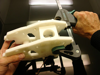
Before printing all the parts you should print the CALIBRATOR, to check if your parts will fit together. If you have a very hard time putting those parts together, adjusting the horizontal expansion setting of your slicer software can solve that, this setting can vary depending of your slicer and printer but users report to set it at -0.15 is a great place to start.
An infill of 30%, wall thickness 2.5mm, best with no raft, no support(unless specified), use a brim for big parts to avoid warping.
Here is the list of parts and the number of prints needed for the torso:
- 2x: KinectSideHolder
- 2x: KinectSideBack
- 1x: KinectMidFront
- 1x: KinectMidBack
- 2x: InterKinectSide
- 2x: InterKinectMid
- 2x: HomLowFront
- 2x: HomLowBack
- 2x: ChestLow
Here is the list of parts and the number of prints needed for 1 right shoulder:
- 1x ClaviBack
- 1x ClaviFront
- 1x PistonClavi (if you have a trouble fitting this part with pistonbase, you can decrease the X and Y size before printing of 0.1 or 0.2mm)
- 1x Pistonbase
- 2x PivConnector
- 1x PivGear
- 1x PivMit (add support)
- 2x PivPotentioRound or PivPotentioSquare
- 1x PivPotholder
- 1x PivTit (add support)
- 1x PivWorm
- 1x Pivcenter
- 1x servoHolster (add support)
- 1x servoholder
- 1x shoulderconnect
STEP1:
Follow the step1 in « Building the bicep of InMoov » for to extract the potentiometers of your servos.
Here is another solution posted by an InMoov builder (Wayne Kinne) if you can’t open up your servo the way I did it, of course if you have a solder pump, it will be even easier:
Or you can also watch these videos posted by a InMoov builder (by Kaibab):
Here is another set of videos (by Yann Huguenin), in which the technique involved is to remove the solder on the three motor connections, leaving the motor in place instead of removing it:
Or this video:
A PDF for to extract the potentiometer on a JX-PDI2060MG servo:
IMPORTANT: There is a difference though in the last part during re-welding the cables to the potentiometer depending if you build the right or left shoulder.

Weld the cables this way, if you are building the right shoulder. In this picture the blue replace the green or the black wire depending on your servos.

Weld the cables this way, if you are building the left shoulder. In this picture the blue replace the green or the black wire depending on your servos.
This will allow your servo to turn the opposite way making your initial 0 position becoming your 180 position. And your initial 180 position become your 0 position. I hope you get the idea. This will be done on both servos used in each shoulder. Now let start the assembly.
STEP2:
If you plan on building both shoulders you should repeat most of the following steps explained bellow for the other side of the body.
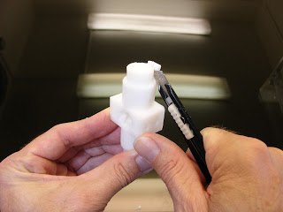
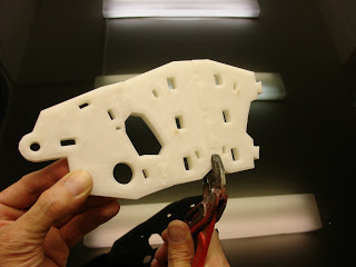
Remove the pre-built support under « PistonBase »
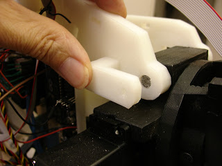
Make sure « PistonClavi » can run freely inside. If your prints are a bit too tight you can ease it with grease. I had to fine tune my printer for those parts to get the right setting.
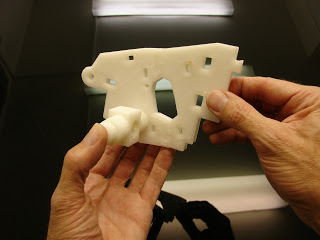
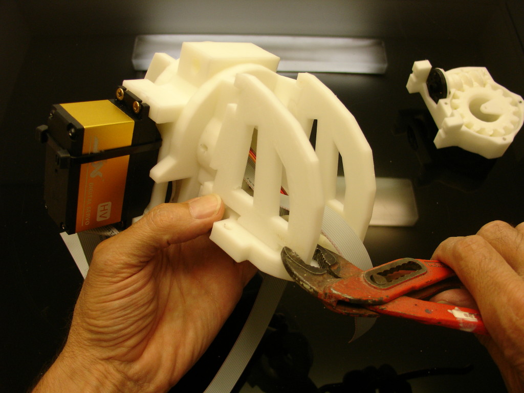
Assemble together with your favorite pliers, « PistoBase », « ClaviBack » and « HomPlatback+ ».
If you are building in PLA, you can use a hot air gun to get parts warmed up to get them to fit easier, it avoids braking parts.
Make sure that « PistoBase » can rotate smoothly.
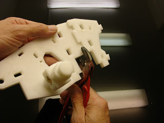
Add « HomPlatback-« to « HomPlatback+ »
Here you can see my favorit pliers in action.
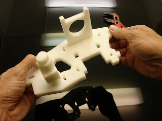
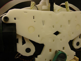
Add « ThroatHole » to « HomPlatback-« to « HomPlatback+ »
« ThroatHole » has been modified since this picture.
Time to assemble the front. Mount together « Sternum » to « ClaviFront ».
Sorry this picture shows the first version I made but it’s pretty close, check the next picture.
This is the shape you will obtain with the last version and the last « ThroatHole » in the back.
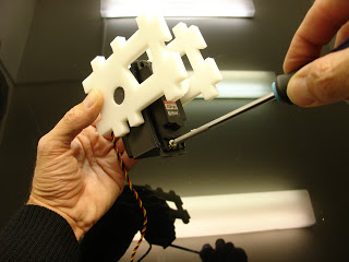
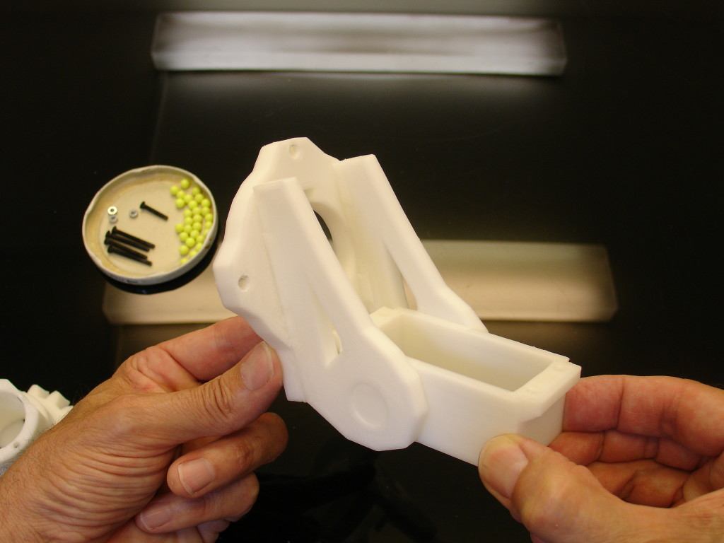
Mount together the two « ThroatLower » and « ServoHolster ».
This servo, set in the middle of the torso, is for to move the head up and down and can be added later if you wish, but the holster should be set already in place.
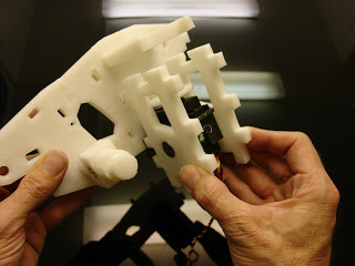
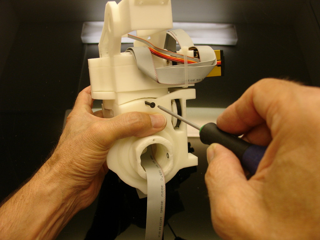
Mount this assembly to the back assembly. Check on the picture the plots and the position of the servo. Front clips and back clips are different.
Add the front assembly to the rest.
You can help yourself with clamps. It should all fit nicely. You can add acetone to glue parts together, but I haven’t done it yet and it holds together since a few weeks of tests.
STEP3:
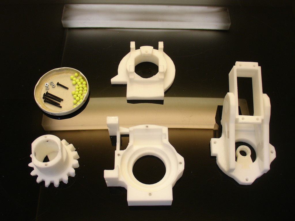
In this part of the tutorial you will see yellow BBgun balls of 6mm.
Carefull with the type of grease you use. Some grease tint the printed parts or even disolve the BBGun balls. The white grease that you see on this picture turned out to be terrible with the plastic BBGun balls, I had to replace all the balls with steel balls.
These of course can be replaced with steel balls instead. Also in this part of tutorial I am using other servo than the HS805bb. These other servo seem to be very good and the price is reasonable. (Ref PDI-HV2060MG)
Insert 3mm nuts into each nut shell, these can pushed in with a pair of pliers.
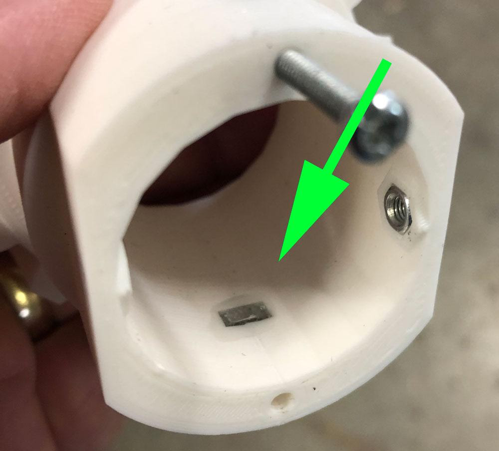
Secure the nut with melted ABS or epoxy glue.
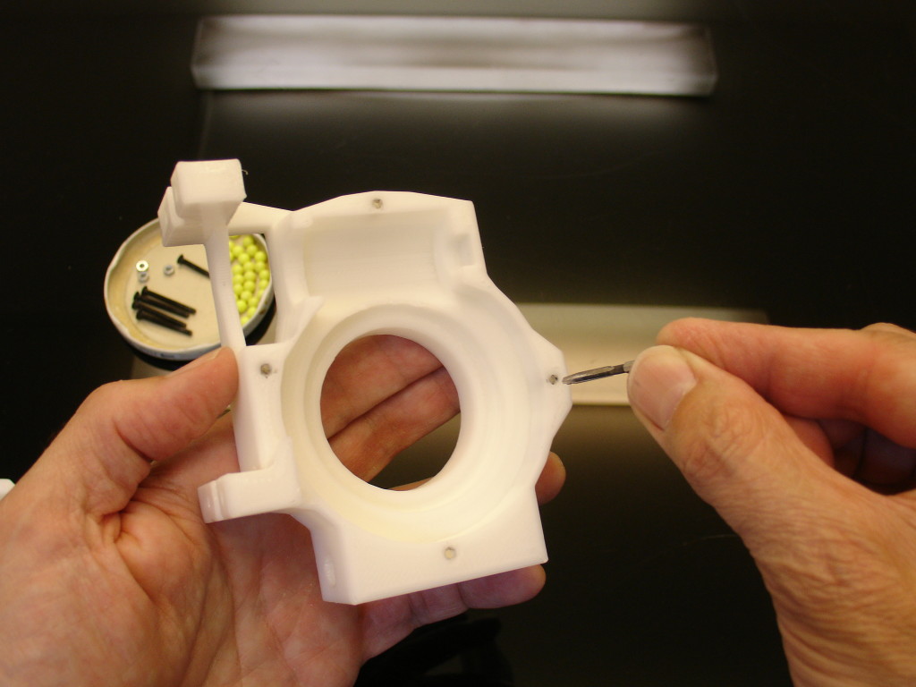
Redrill the holes and make sure your 3mm screw engages correctly into the nut.
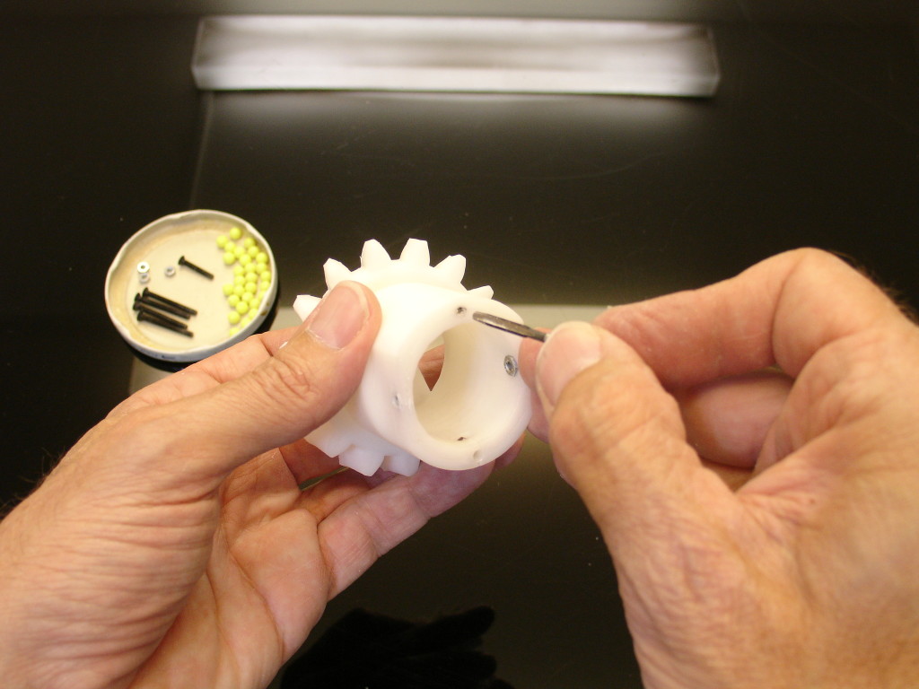
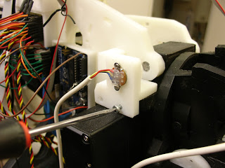
Make sure that the potentiometer shaft fits perfectly into the hole. If necessary use a small file.
Also make sure the body of the potentiometer fits well into the PivPotentioRound (you might need to use the squary version according to your potentiometer)
Assemble and glue together PivTit, ServoHolder. ServoHolster needs to be inserted but should NOT be glued in order to rotate freely.
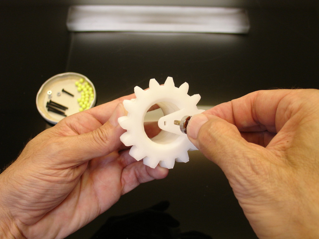
Press fit PivPotentioRound into PivTit. Normally there is no use to glue it.
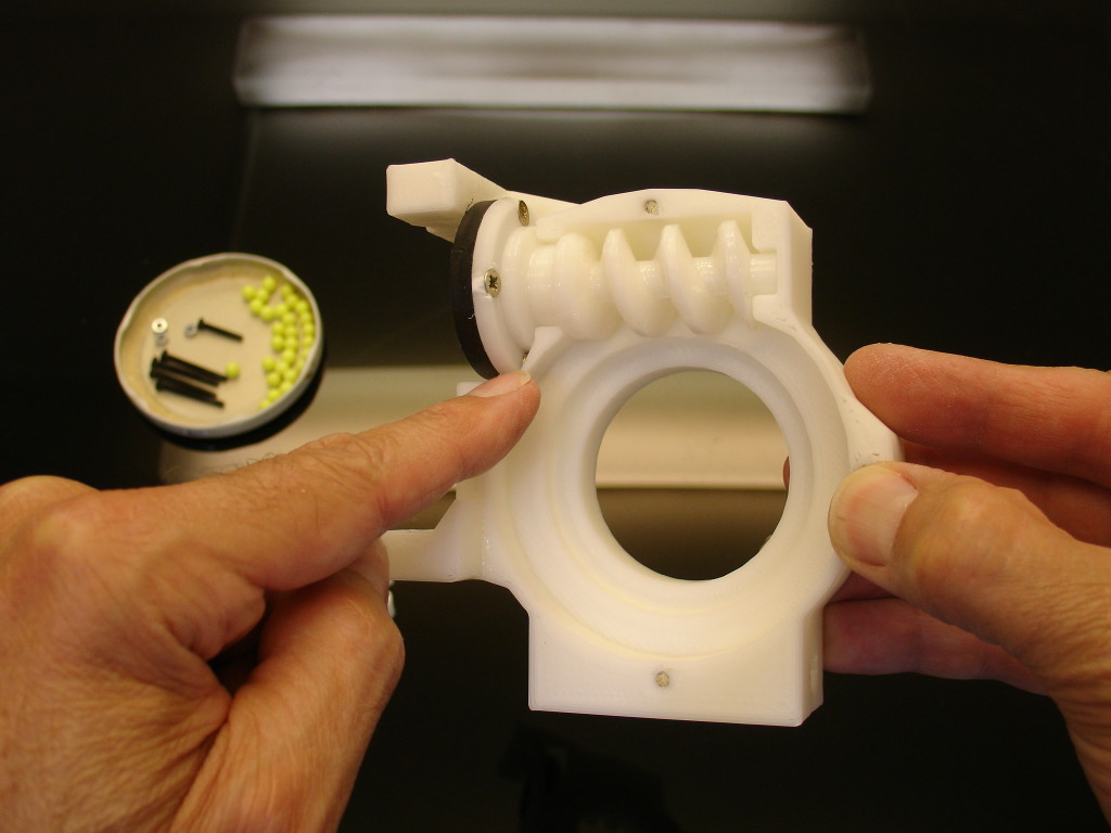
Tab the 4 holes or insert 4 nut of 3 mm on the back of PivCenter.
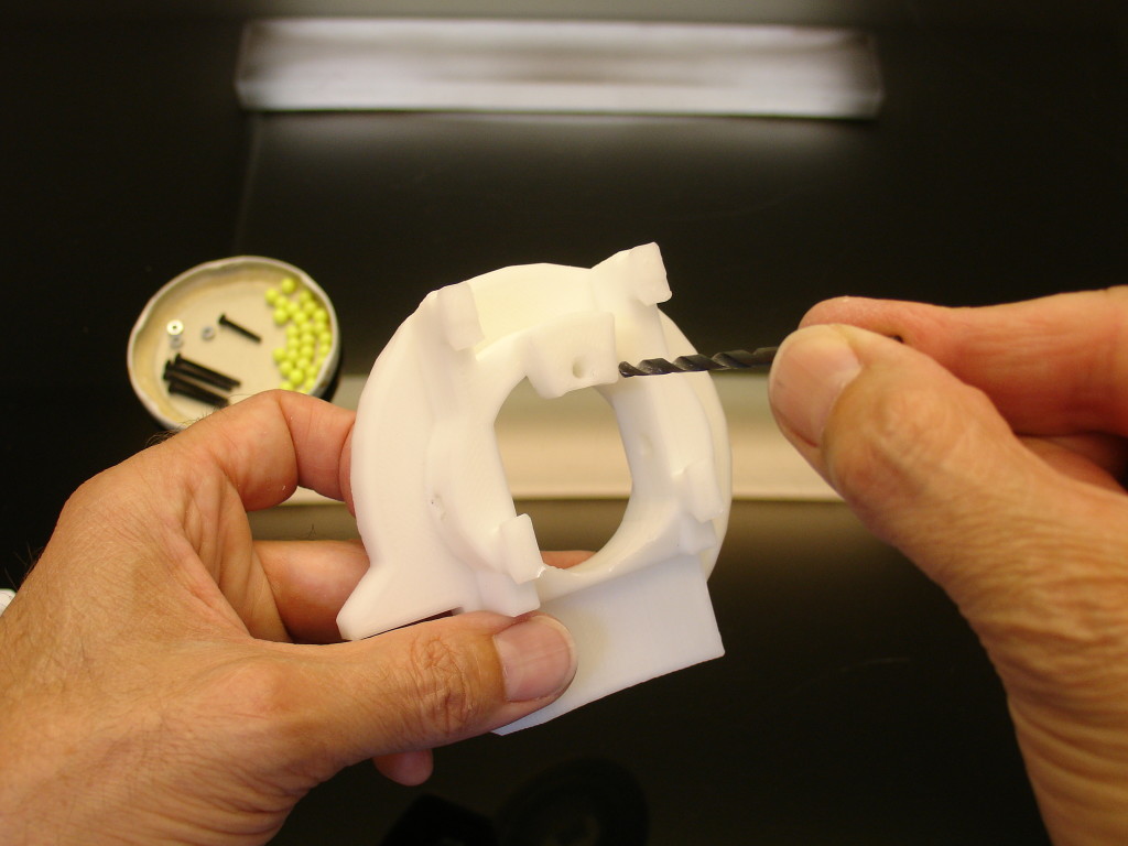
Redrill the holes with a 3.5 mm bore on PivMit.
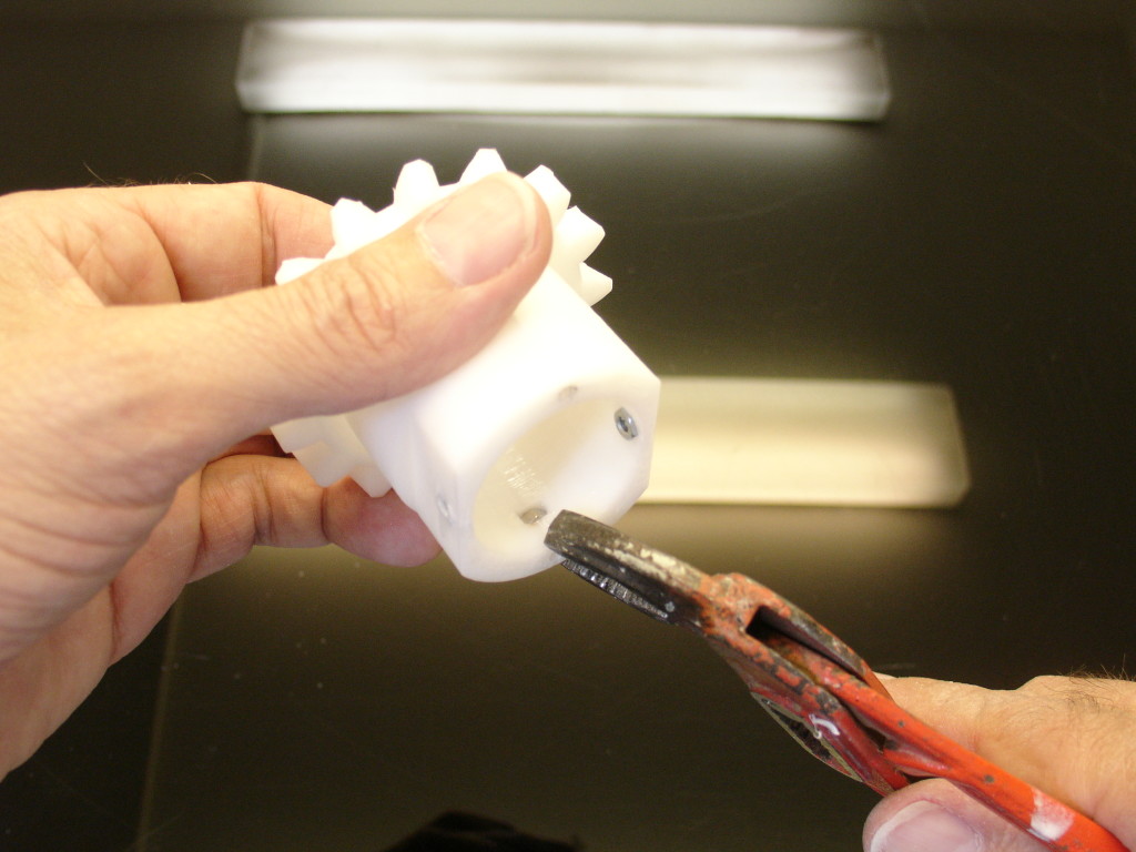
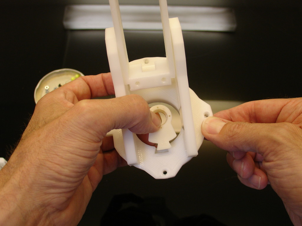
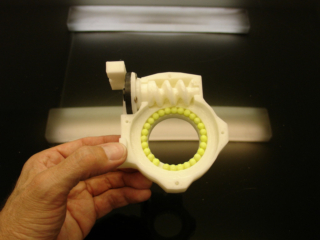
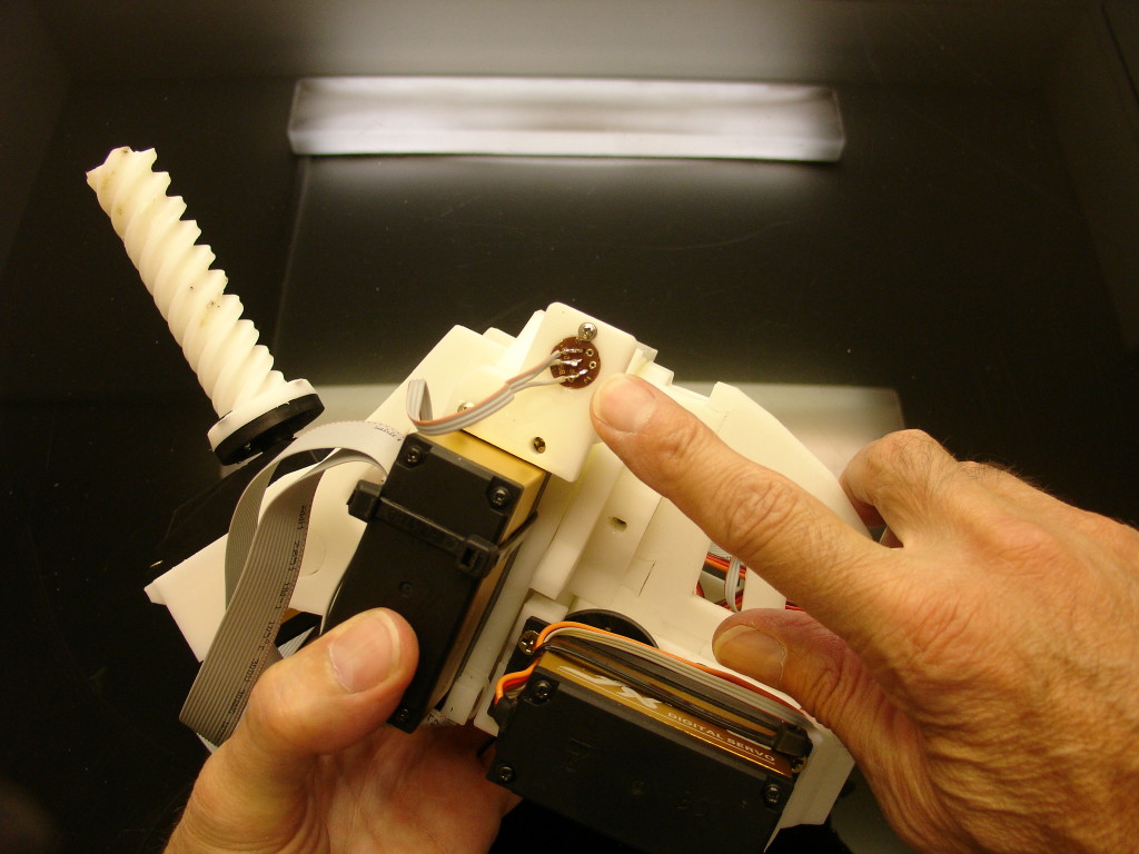
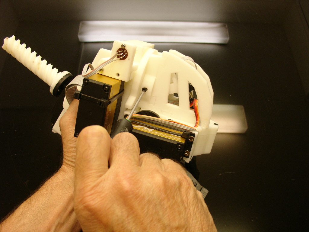
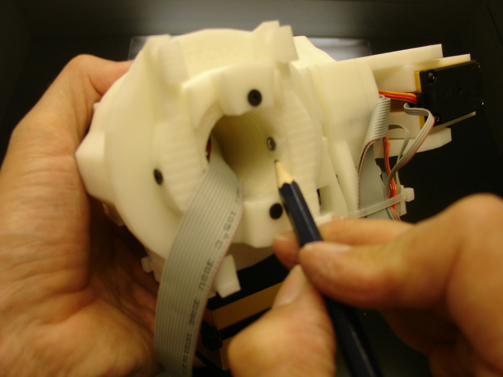
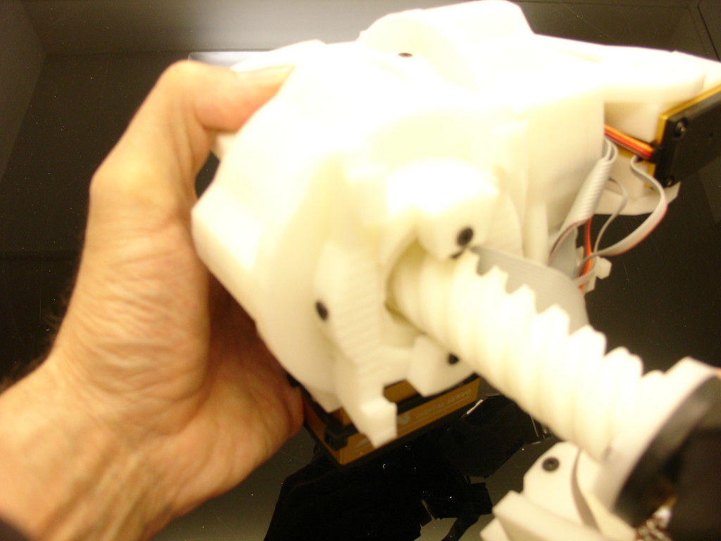
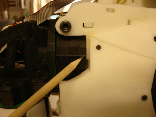
Screw PivWorm to the servo horn wheel(part that comes with your servo). Make sure that PivWorm is well seated in PivCenter and can rotate manually. Also the screws shouldn’t hit the edge that I’m pointing with my left index finger.
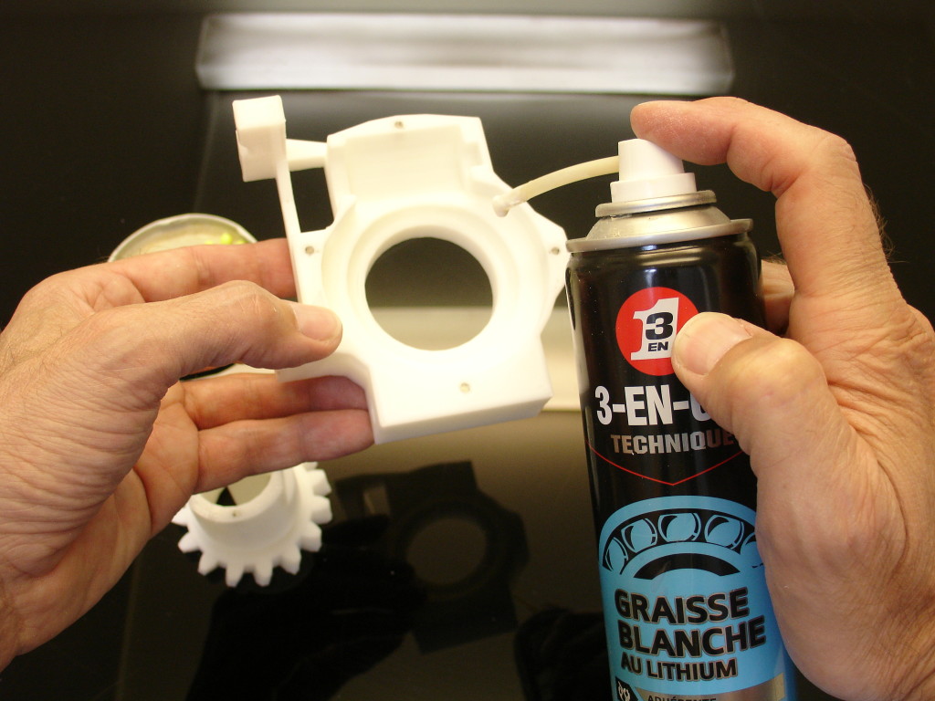
Add grease. Carefull with the type of grease you use. Some grease tint the printed parts or even disolve the BBGun balls. The white grease that you see on this picture turned out to be terrible with the plastic BBGun balls, I had to replace all the balls with steel balls.
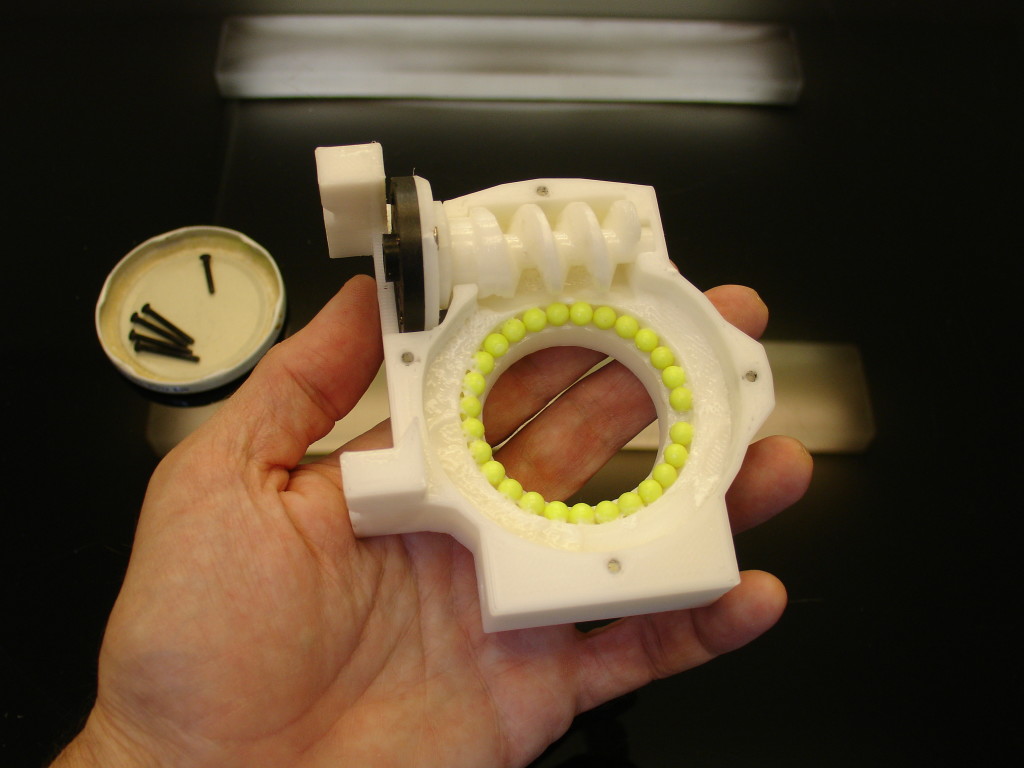
Add the Balls. Here you will need a total of 27 balls.
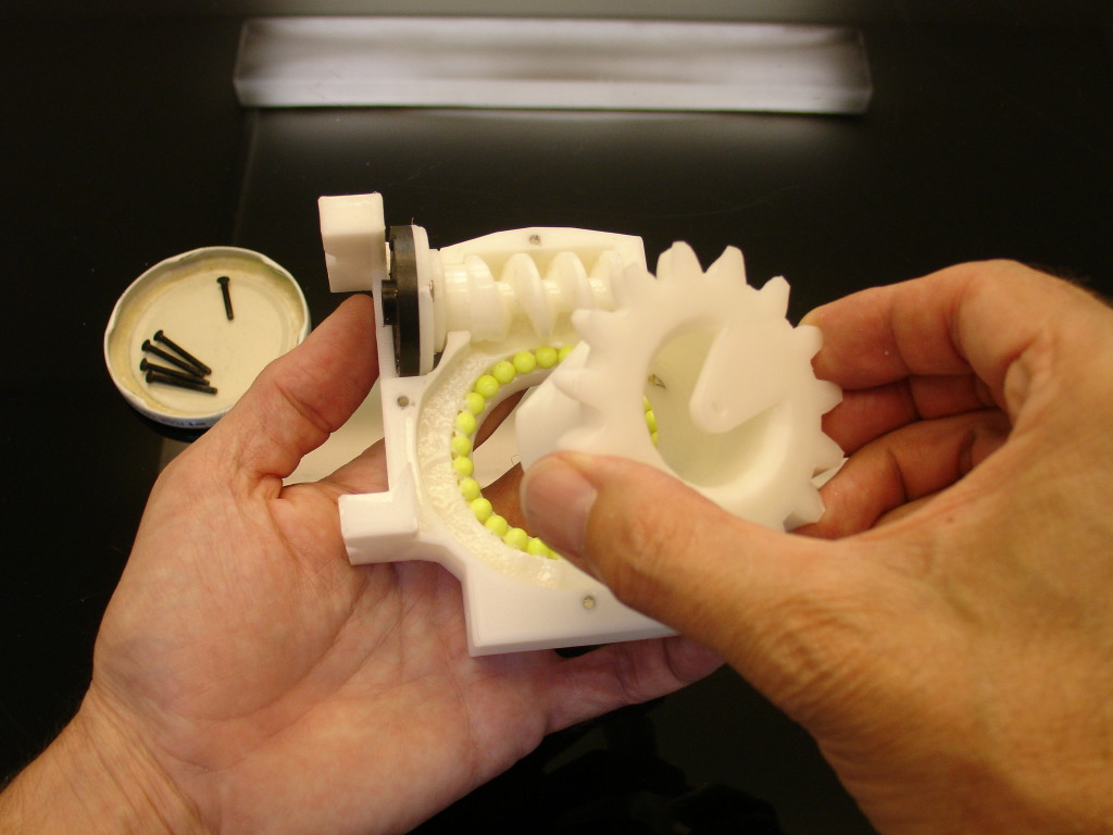
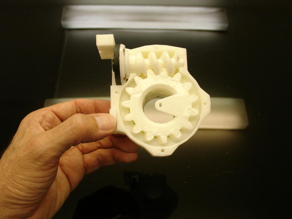
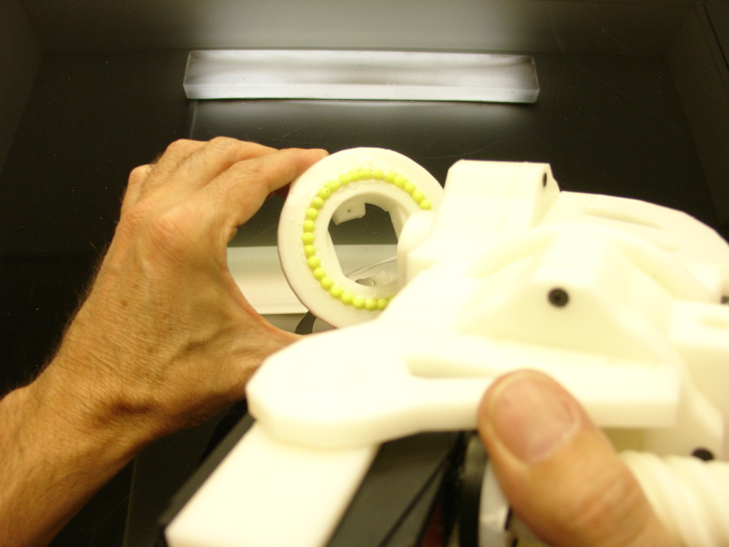
Insert PivGear.
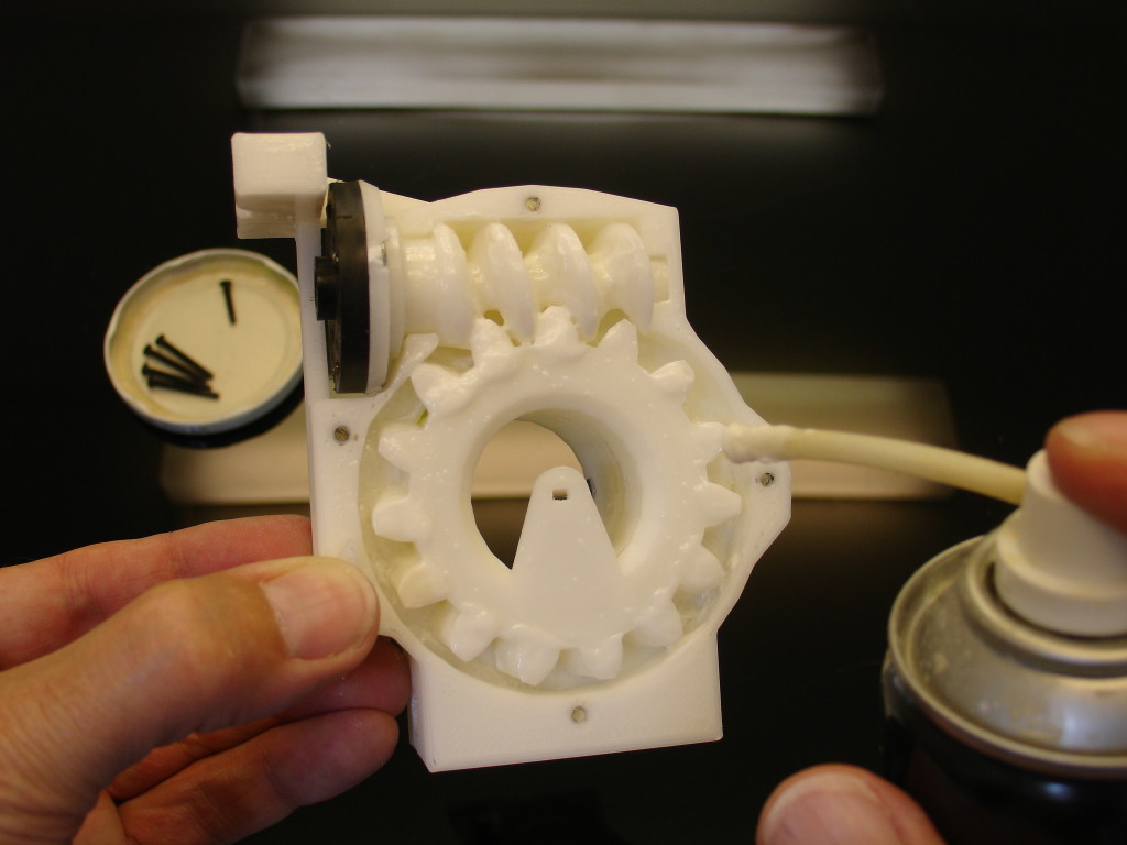
Add more grease everywhere on the teeth. See how PivGear is positionned on my picture, make sure it will be turned this way when we will later add the potentiometer.
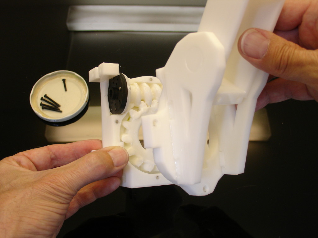
Mount PivTit.
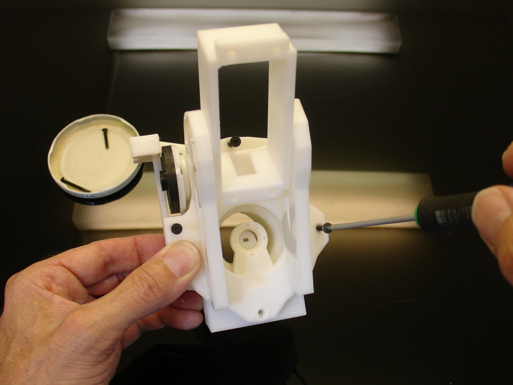
Screw PivTit to PivCenter with 3mm screws. I use hexagonal screws with a length of 35mm to reach the nut on the other side of PivCenter.
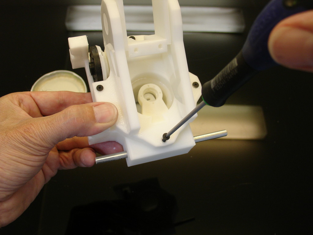
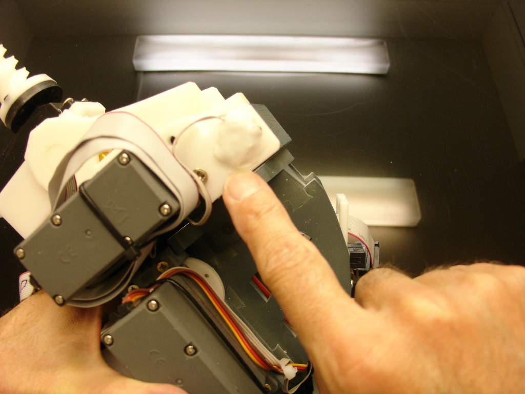
This screw needs to be shorter (20mm maximum) in order to let the 8mm shaft rotate freely.(Chrome shaft in this picture)
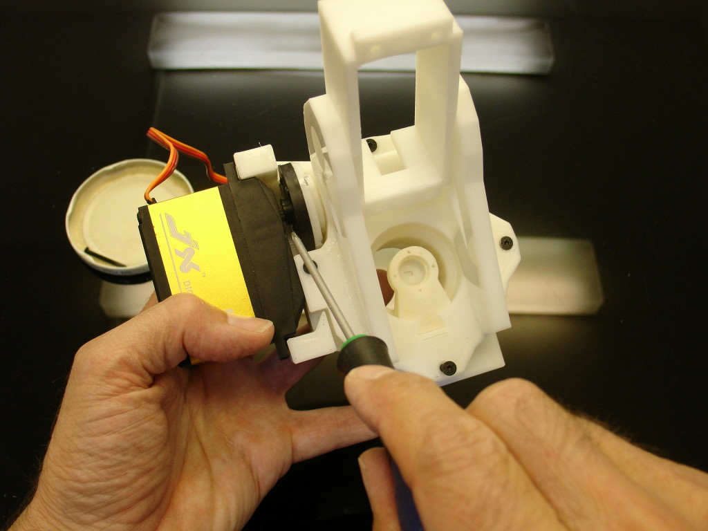
Engage the servo on the servo horn wheel. Make sure it is fully engaged, some horns are a bit nasty and hard to manually press fit. So don’t break something. As you see in this tutorial, I am using another model of servo than the HS805BB and it was really hard to press fit.
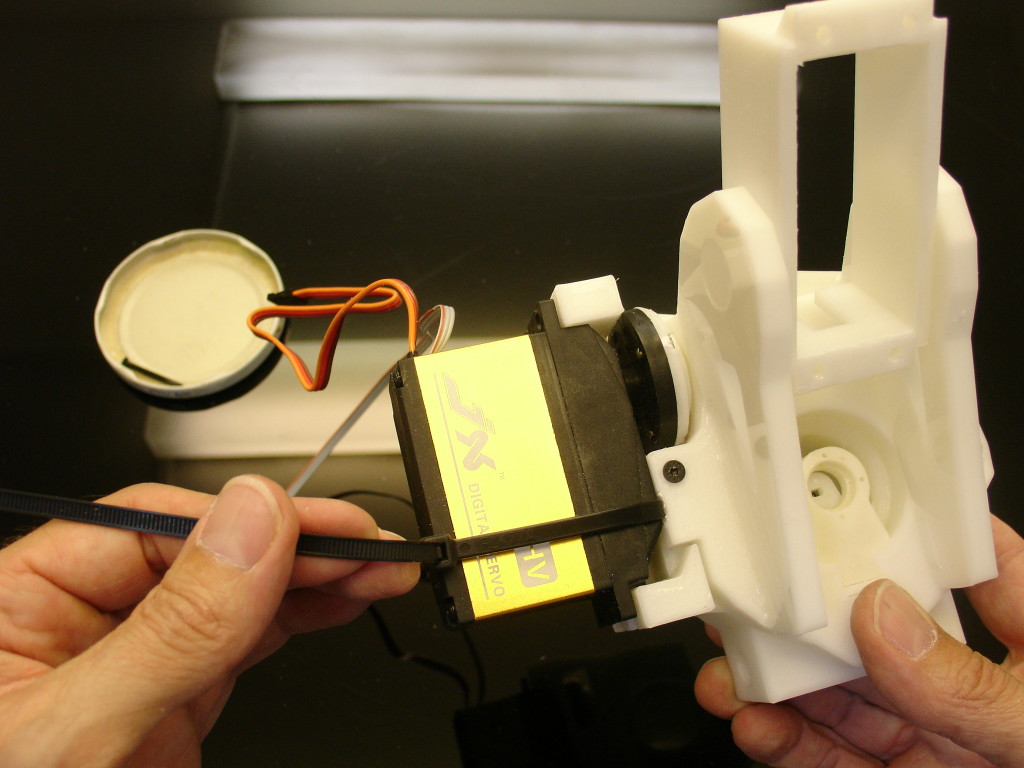
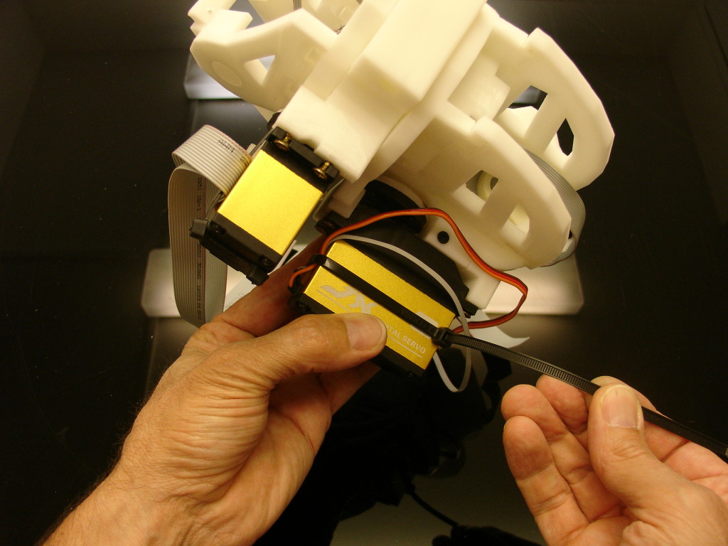
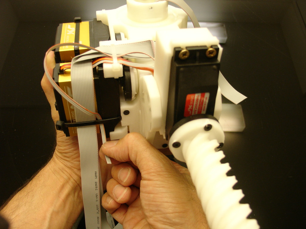
Prepare and add a plastic zip around the servo, see how and where the zip connector is placed, it is important to do the same for futher assembly. Don’t tight completely the zip yet, we will pass through the ribon and cables later.
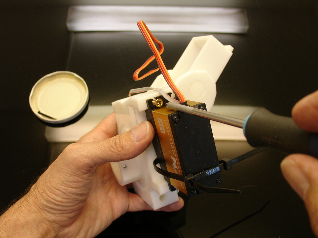
Now you can add the 4 screws to fix the servo. I use standard Philips wood screws of 3,5 x 16 mm but you can fit other sizes as well.
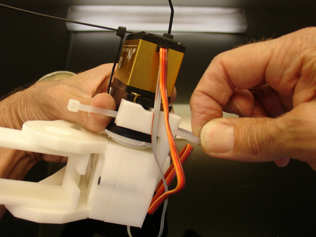
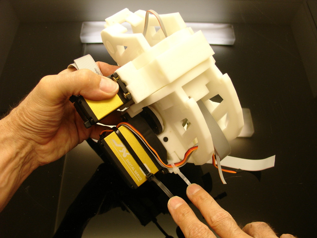
Insert another plastic zip as show.
Pass through both cables coming out of your potentiometer. (servo and potentiometer extension)
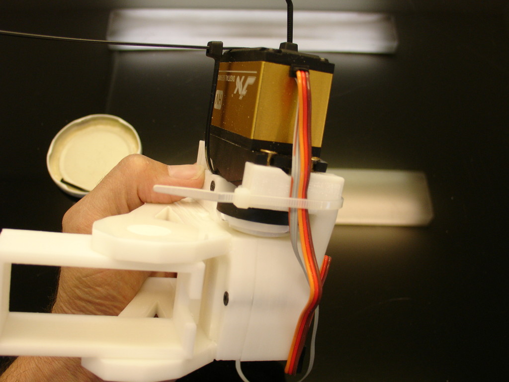
You can tight the plastic zip, respect its position as show on the picture. Cut the extra zip length.
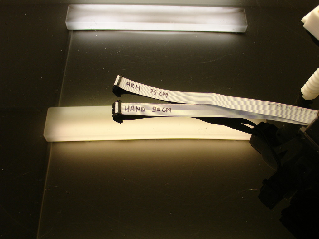
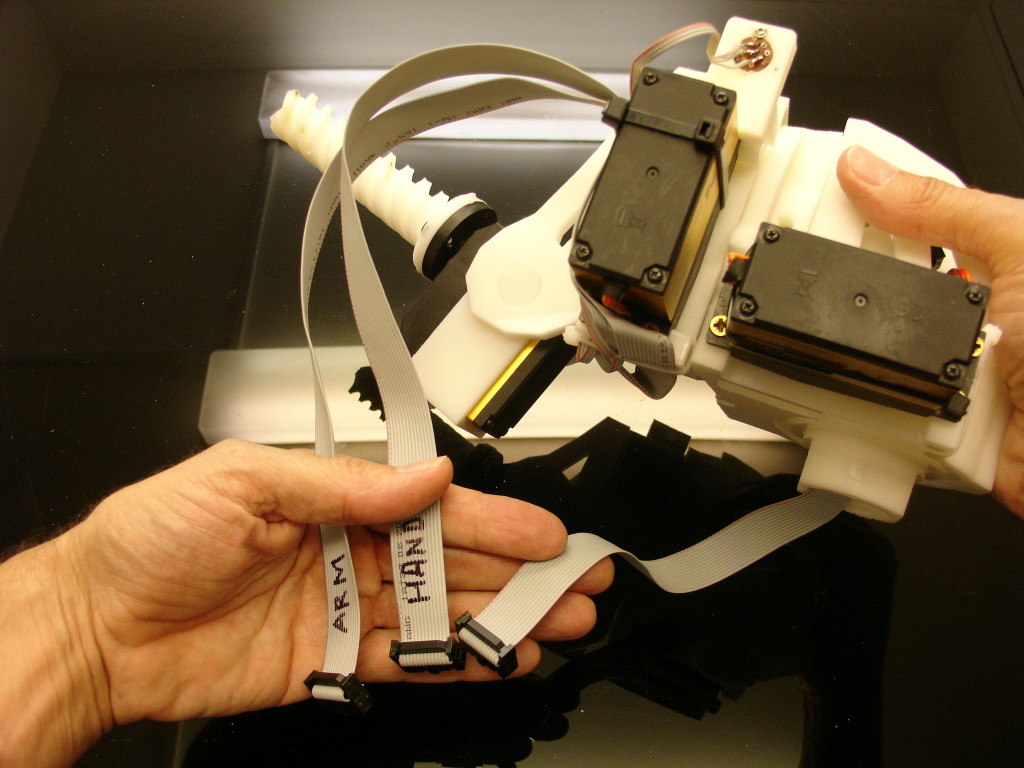
Now lets prepare and cut the ribon cables for the arm and hand. You can see the necessary length noted on the ribons. Do not fix the headers yet!
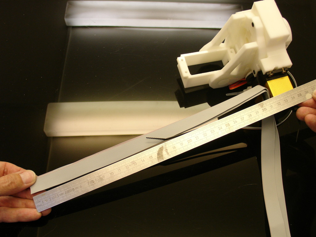
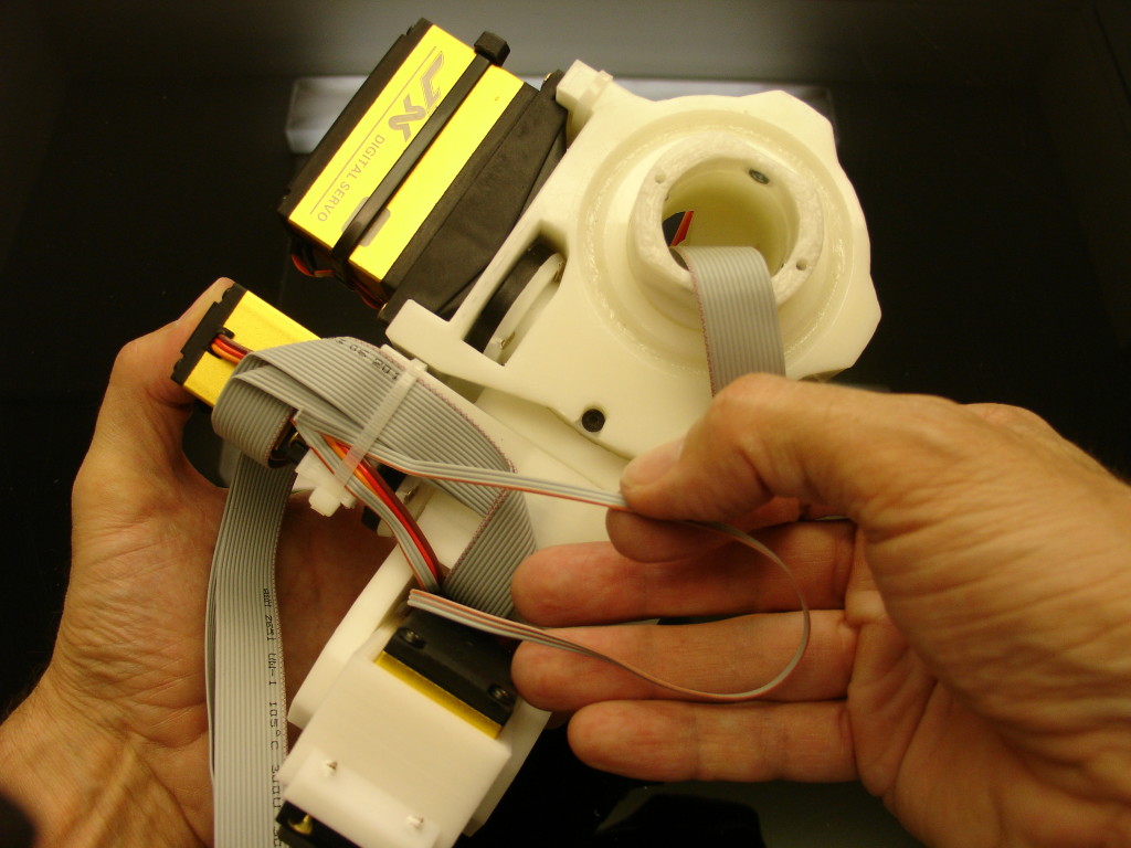
Fold both ribbons at approximatively 30cm, and pass them through the black plastic zip. Note on my picture how the red lining(Vcc+) of the ribbon is set.
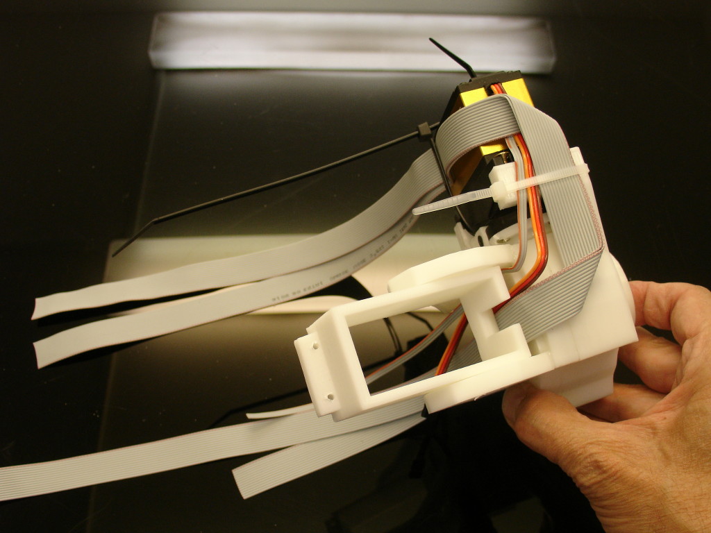
Fold again the ribbons and pass them through the second white zip. Fold once more the ribbons and run them down as shown on the picture.
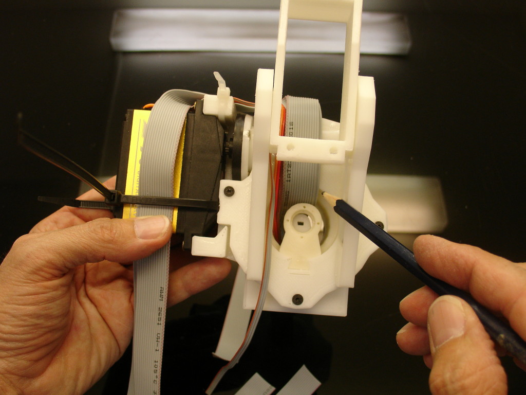
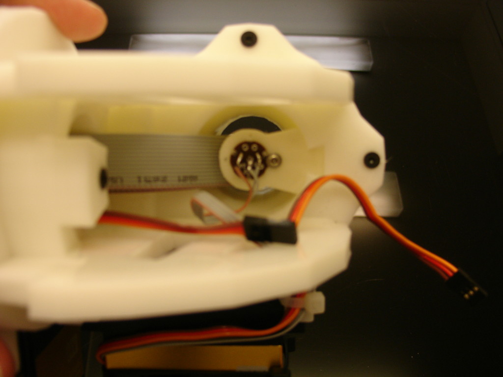
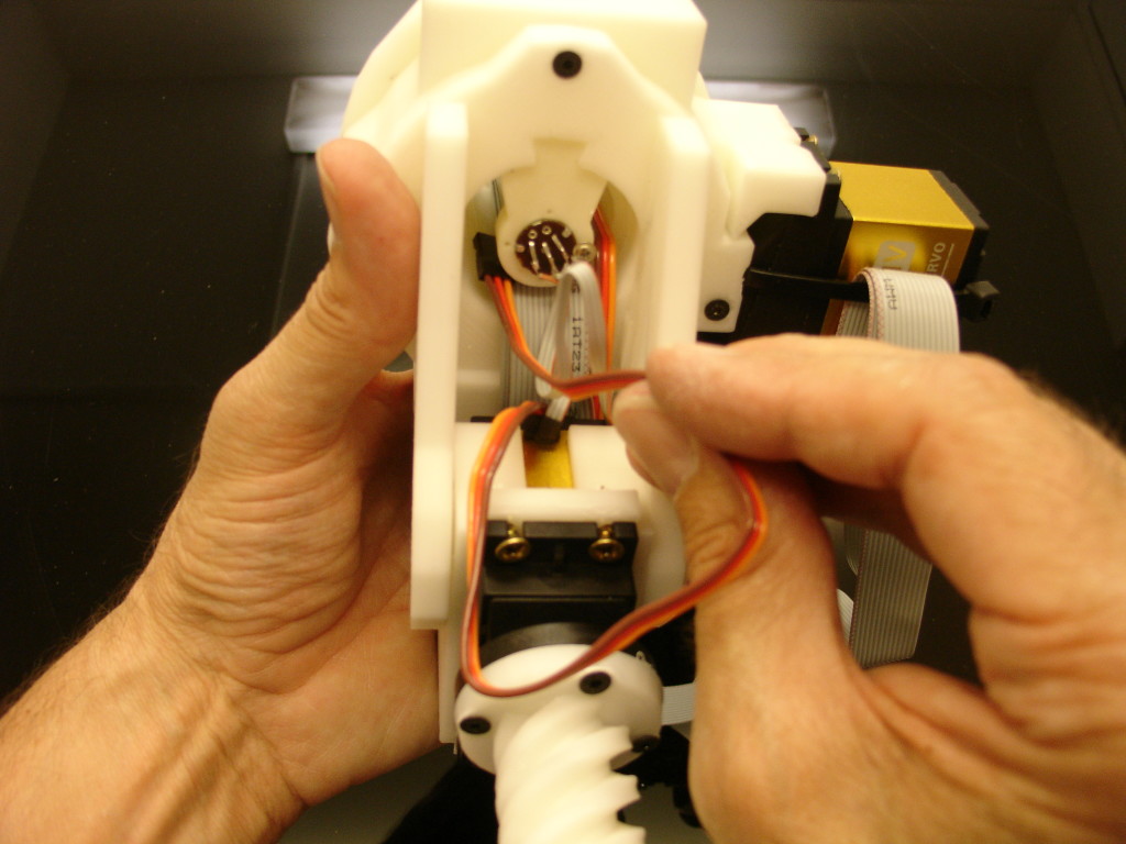
Now pass both ribbons and the servo cable through PivGear as shown.
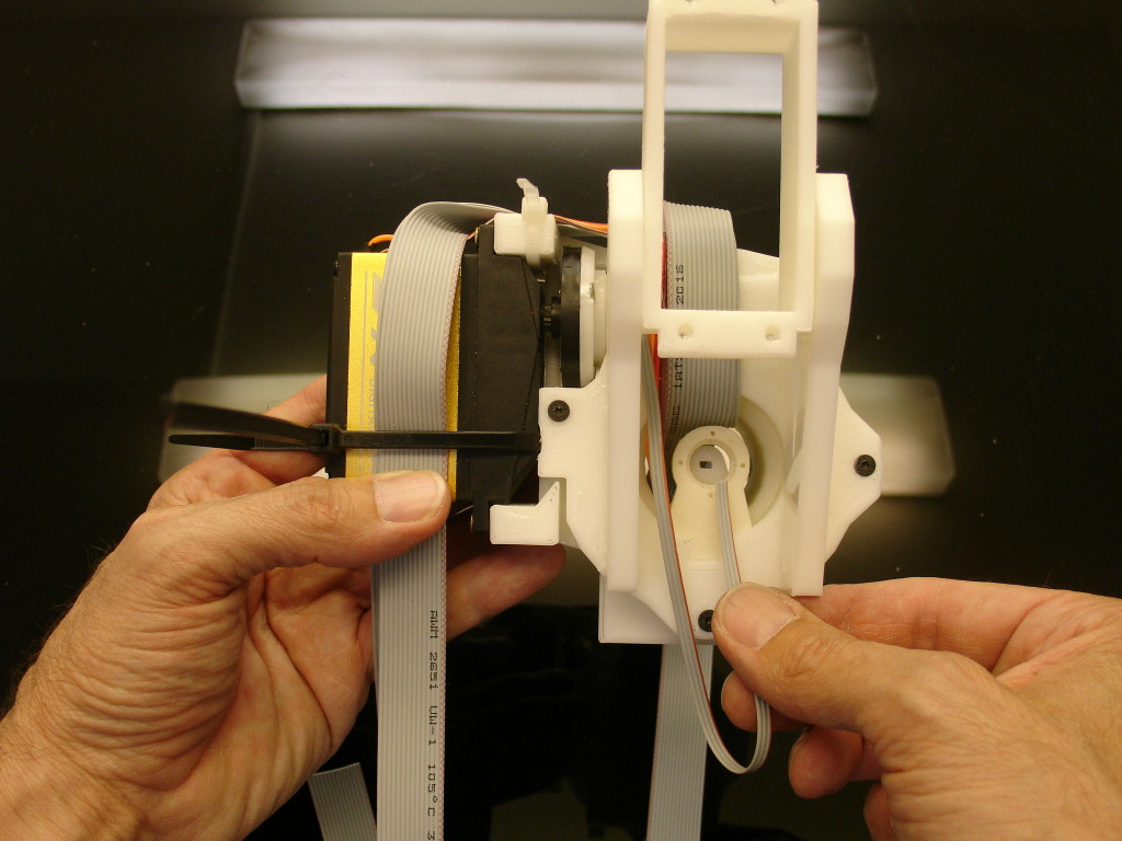
You can see here I am holding the cable for the potentiometer which doesn’t need to run through PivGear. (As info: when I prepare the extracted potentiometer, I add a 35 cm extention of cable which is largely enough as you can see.)
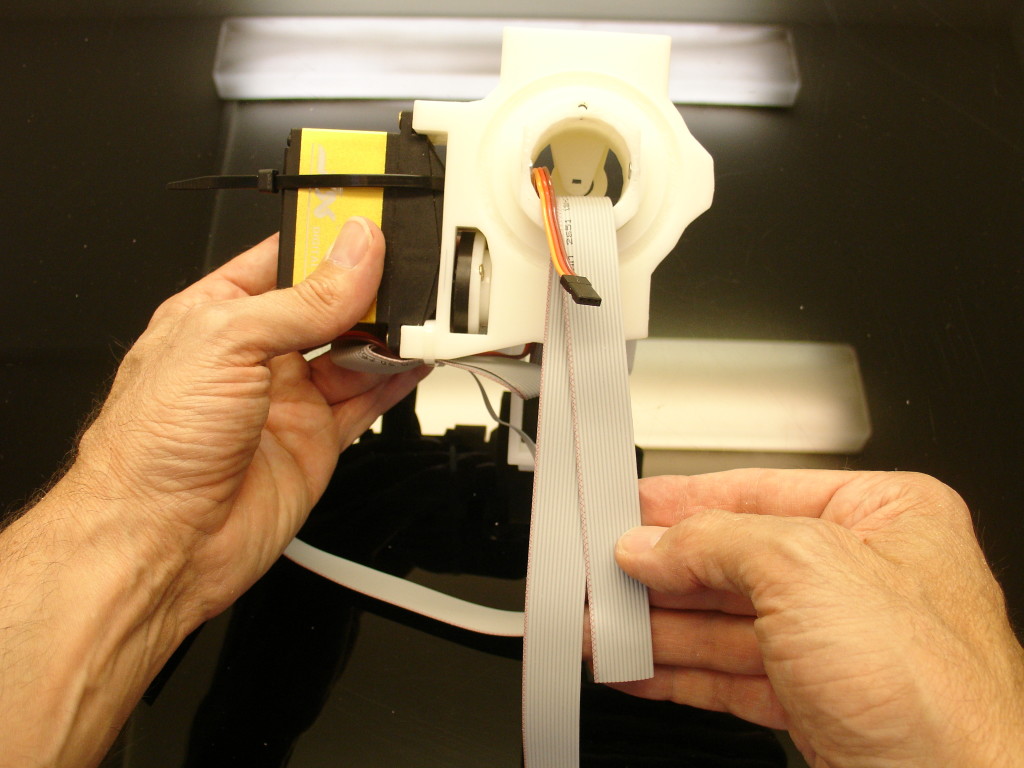
From the other side it should look like this.
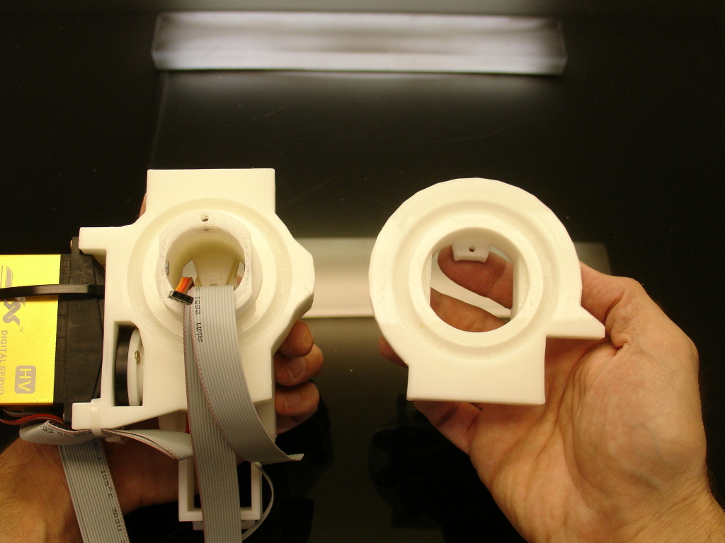
Get PivMit part.
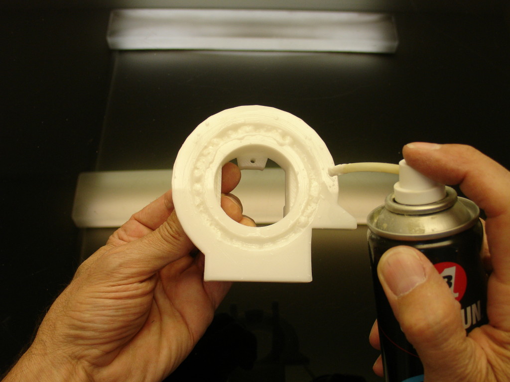
Add grease on PivMit in the ball joint.
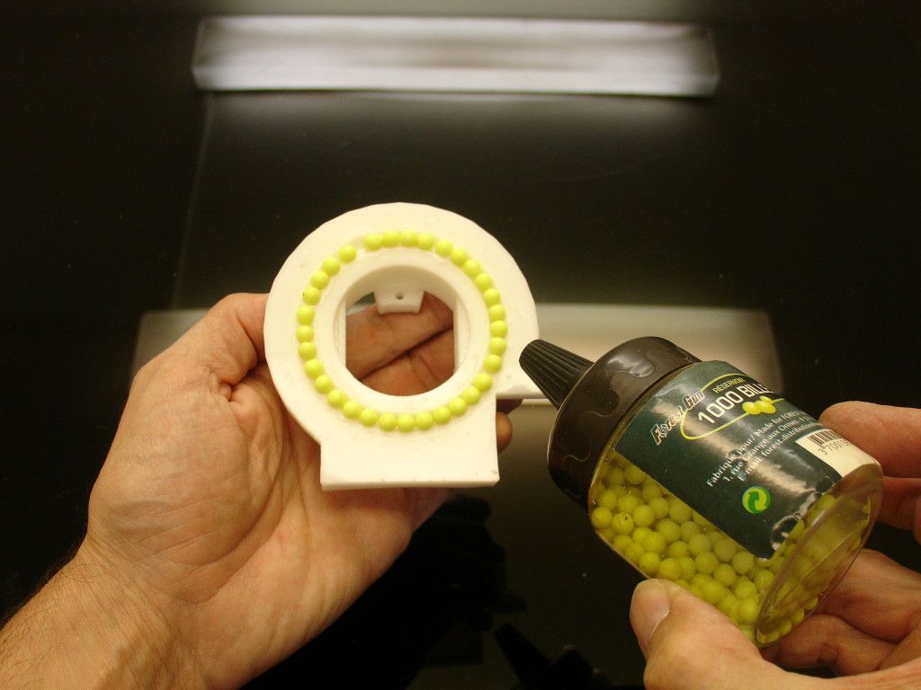
Add 31 balls.
Insert PivGear into PivMit as shown on the picture. Be carefull not to put it upside down.
Add WITHOUT tightening a 3mm screw of 30mm length to reach the nut. This screw is to adjust the pressure on the ball bearing.
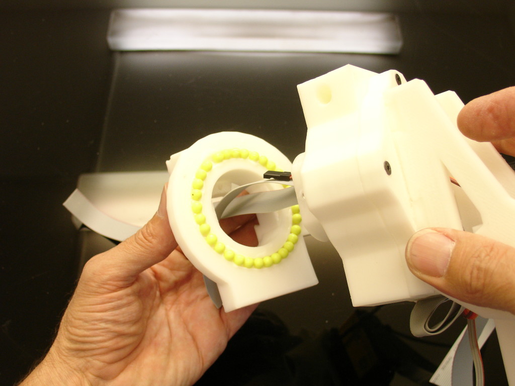
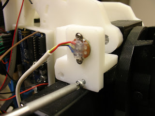
Now we can mount and solder the cable to the potentiometer. Note the slight rotated position of my potentiometer, your should be approximatively the same. Later you might need to re-adjust its position.
Lets prepare RotCenter with grease and 27 balls. Lets also prepare RotWorm screwed on the servo horn wheel.
Lets add RotGear and grease. Note the position of RotGear on my picture.
Mount RotTit as shown to PivMit. Do not over tight the adjusting screw, it is only meant to adjust the pressure on the ball bearing. Press fit PivPotentioRound into RotTit.
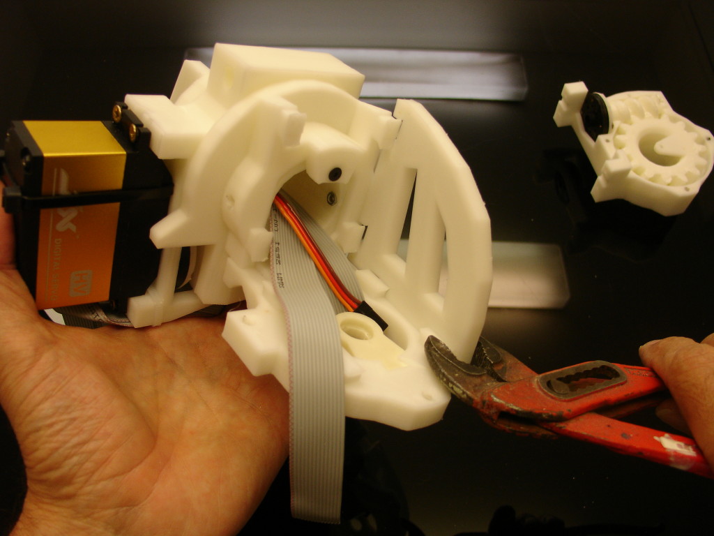
Mount PivConnector, use pliers to press fit them. In case it is very hard to fit them, you can use a heat gun to gently soften up the parts. (With a well calibrated printer, the parts just fit perfectly)
Mount the second PivConnector. Glue with acetone all four parts together, and do it well, this is going to take a lot of pressure.
Mount RotCenter to the whole assembly as shown. Make sure that RotGear is still in the correct position as shown.
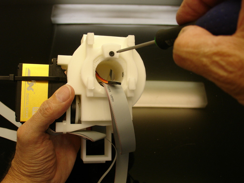
Add a 3mm, length 30mm screw through the bottom of RotCenter to reach the nut on the other side.
Add the other three screws of 3mm, 30mm length by the top as shown.
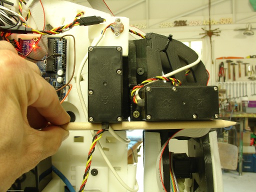
Time to mount the second servomotor.
Add and tight the four standard wood screws 3.5mm x 16mm.
Add a zip tight (black) over the two cables coming out of the servo as shown. Cut the the extra length of the zip.
Put a second zip tight (white) to hold the cables and run them as shown through PivConnector. Cut the extra length of the zip.
Add and solder the potentiometer. Make sure it is mounted as mine. Later you might need to adjust it’s rotation.
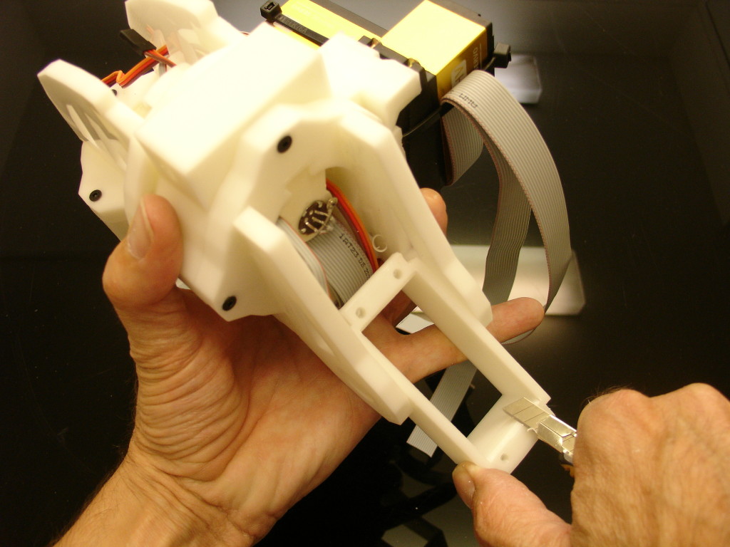
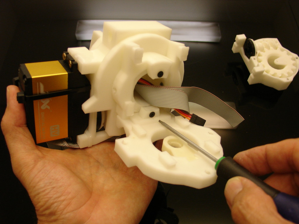
Trim the edge with a blade on ServoHolster, this will help to insert the servomotor. Depending on the model of servo motor, it can be a bit tough to push it in.
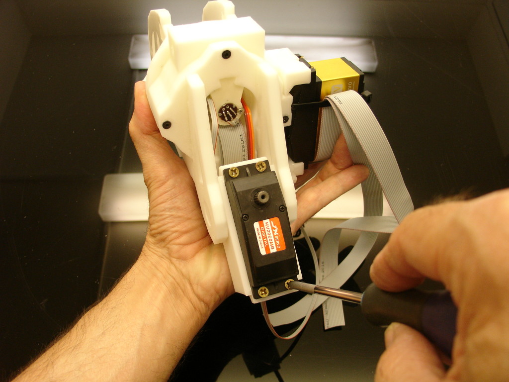
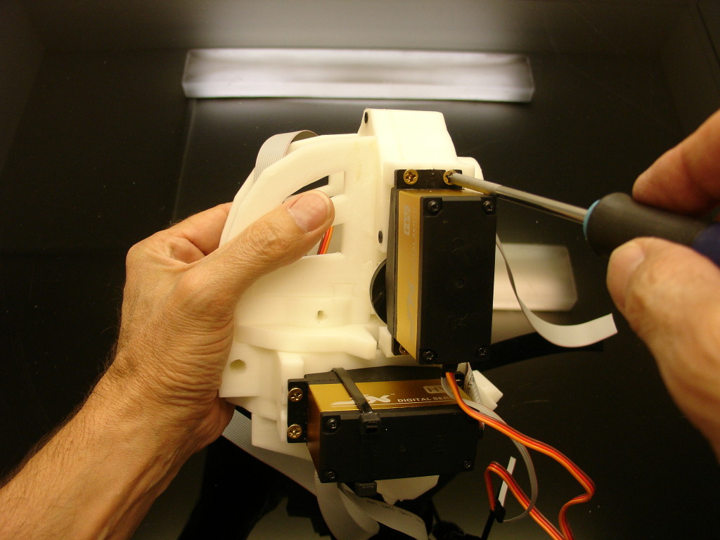
Add and tight the four standard wood screws 3.5mm x 16mm.
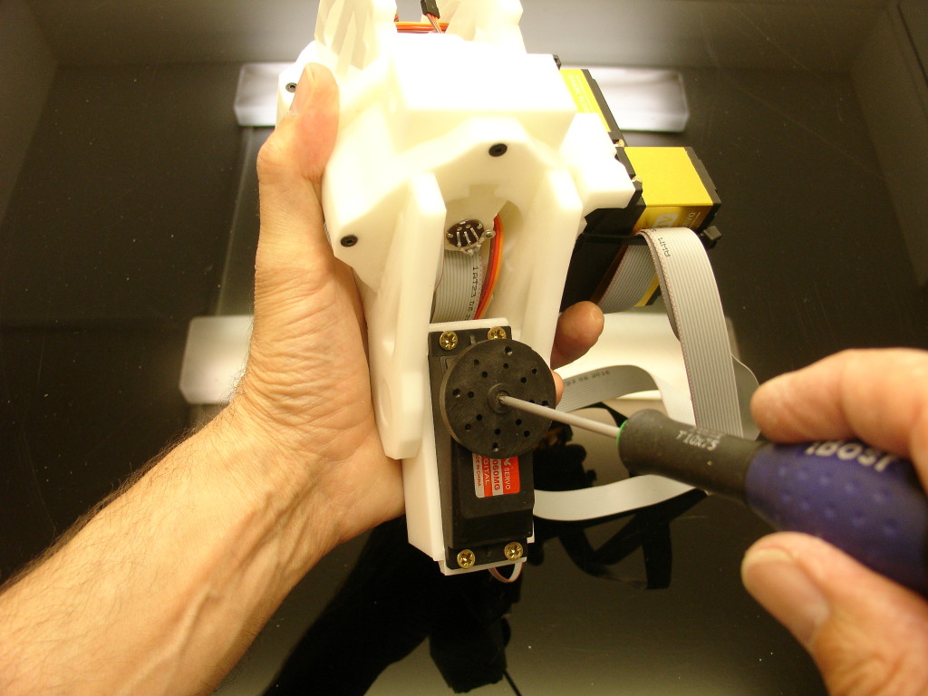
Mount the servo horn wheel to the servomotor and fix the 3mm screw delivered with your servo. Make this tight, this screw tends to loosen up with time.
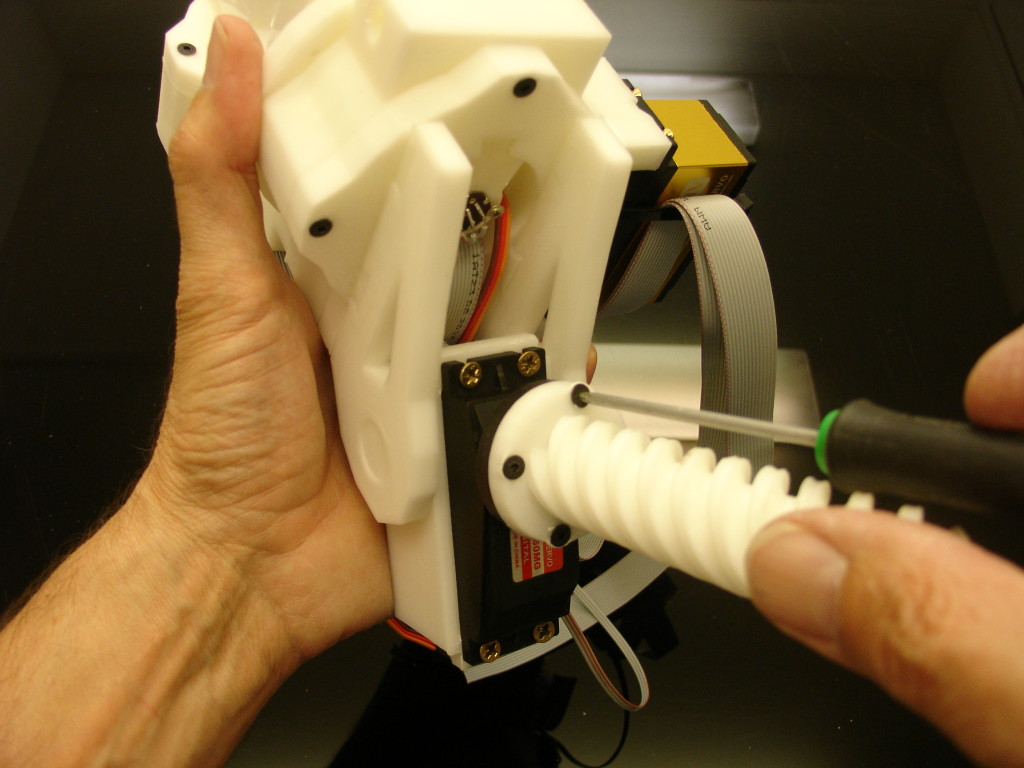
Mount PistonClavi to the servo horn wheel. I use four hexagonal screws of 3mm, length 12mm, but you can also use some small wood screws.
Run the servo cable into PivGear.
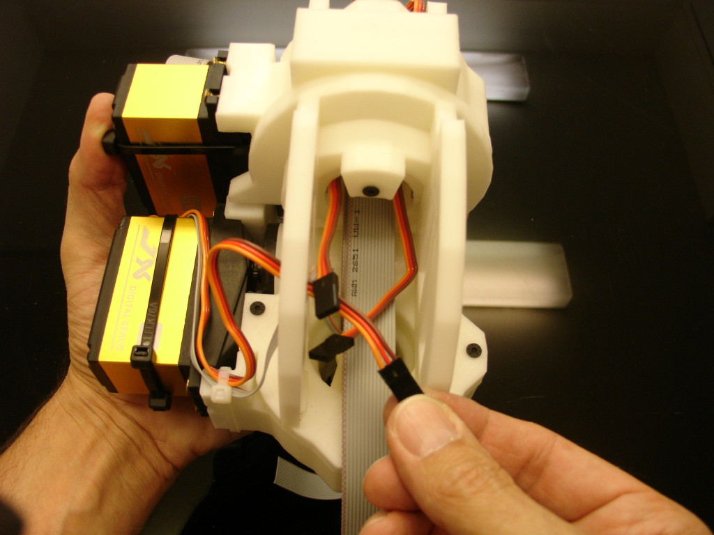
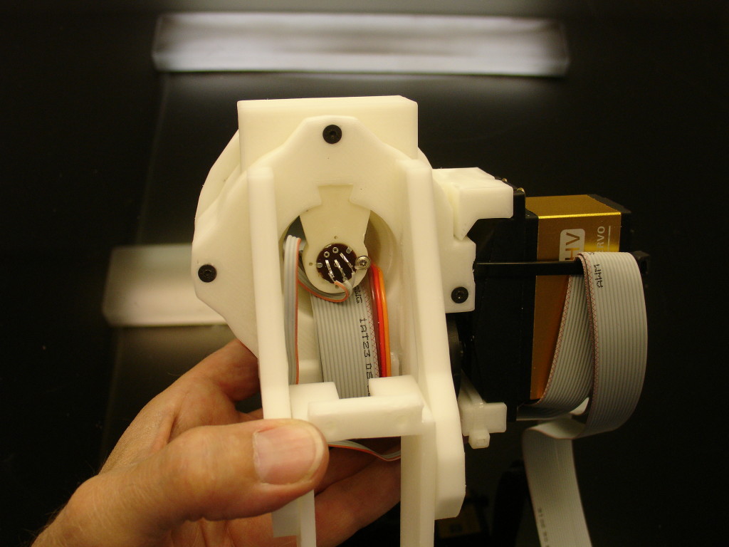
If all is right, you should now have the three servo cables connectors at the same spot.
Run the third potentiometer cable through the zip tight(white) as shown.
Continue to run the third potentiometer cable through the second zip tight(black) as shown.
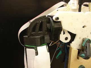
Place the PotHolder as shown, mount and solder the third potentiometer with a similar angle as in my picture. (Later, to fix the PotHolder we will need to remove two screws that hold the servomotor.)
Also later when all potentiometers are well calibrated, it is good to protect the potentiometer solder with some hot glue(Hot glue Gun). But you will do that when you are sure everything is working well.
For info: if you want to remove hot glue, the best trick is to brush some alcohol on it, it will be easy to remove it.
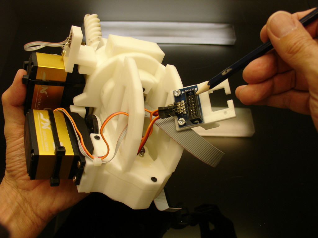
Screw the Arm breakout board to ShoulderConnect. And connect the three servo cables connectors to the respective pins (
see Hardware page & BOM)
-Omoplate pin 11
-Shoulder pin 10
-Rotate pin 9
-Bicep pin 8 (if you already have the bicep built)
Carefull to set the ribon very well seated in the headers as this can cause short circuits. (In this picture the header was doing short circuits and burned the ribbon.)
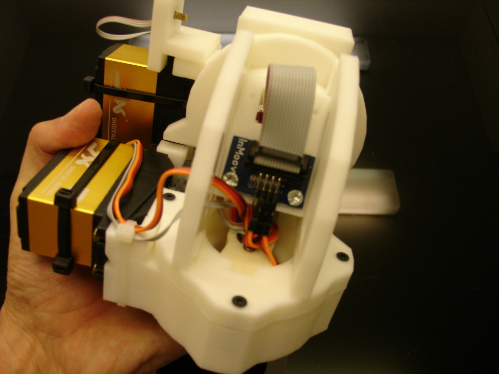
Plug the header to the Arm breakout board.
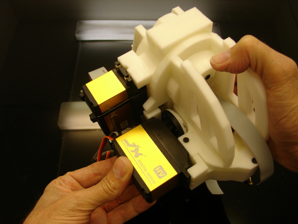
If everything is alright, you should now have something like this.
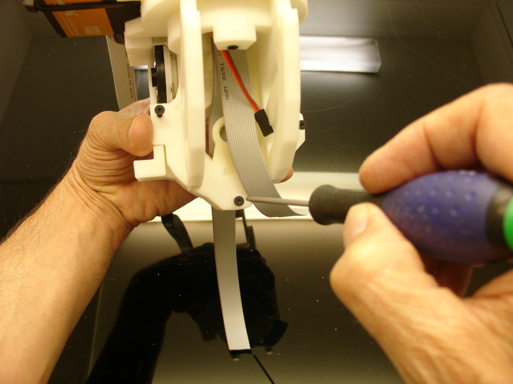
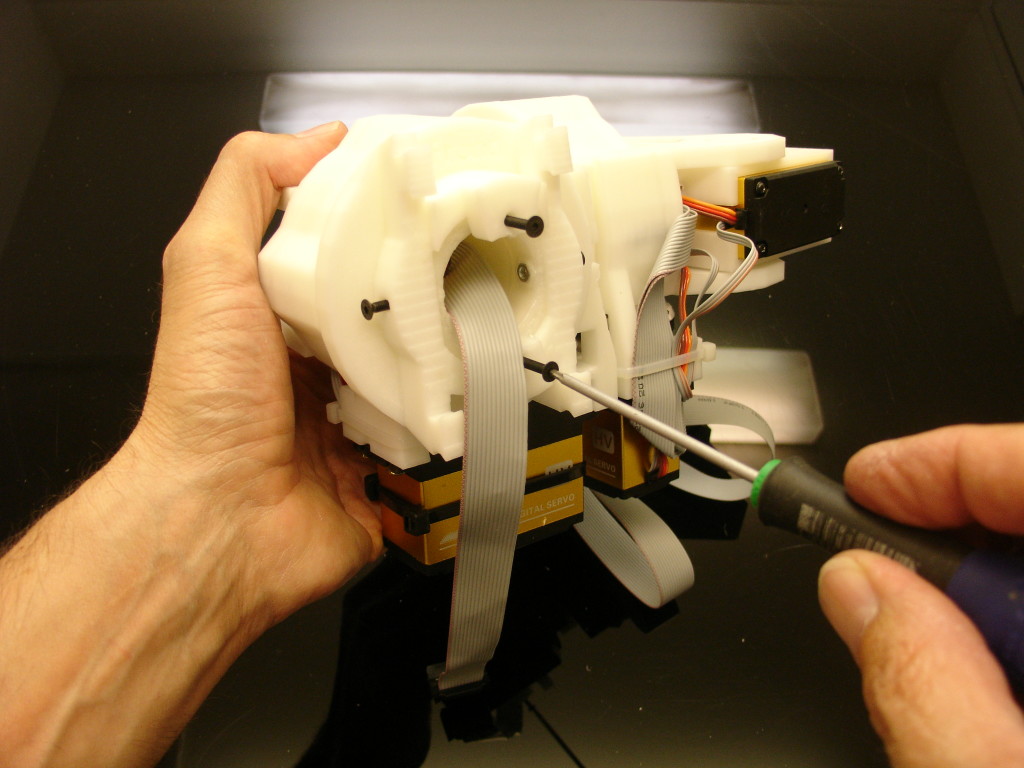
Add the two side screws 3mm, 20mm length. Do not overtight, you might break something.
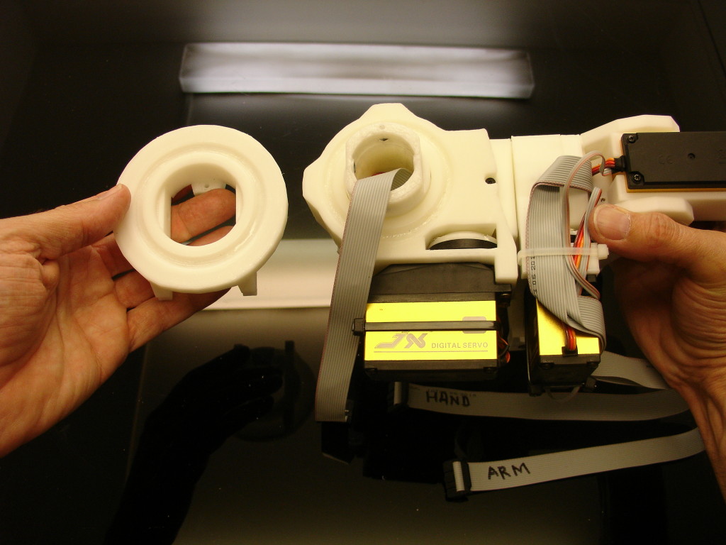
Lets get RotMit part ready.
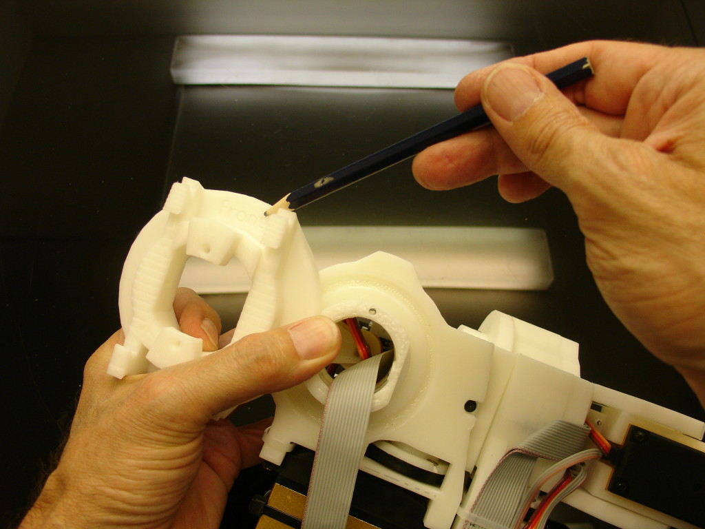
Note that it says FRONT on RotMit. This gives you the way it as to be assembled to RotGear.
Add grease and 31 balls.
Assemble to RotGear.
Add the two adjusting screws of 3mm screw of 30mm length. Do not over tight. These screws are only meant to adjust the pressure on the ball bearing.
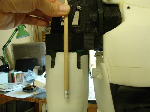
Add and screw the two side screws of 3mm, length 20mm. Make sure they are not longer to the inside. It is important otherwise it might damage the Piston of the bicep.
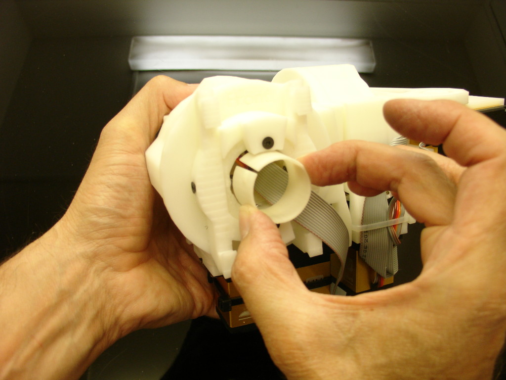
Insert RibbonPusher.
As you see, this is only to hold the ribbon cable to avoid friction against the Piston of the bicep.

Assemble the shoulder to Clavi parts with a 8mm, 90mm length screw. (Don’t mind the ribbon cable, it’s a older version picture)
Attach the bicep parts to the shoulder parts if you have them ready.
In the back of the shoulder clip the first part of « PivPotHolder » to « ClaviBack ».

In your case PivPotHolder has a nut shell for 8 mm nut. (On the picture above it’s a older model)
Remove the two screws attaching the servo and put in place the second part of « PivPotHolder ».
Use longer screws to go through the servo holes.
Connect the two ribbons to your NervoBoards respectively on Arm and Hand.
You are now set to GO for your first test. One thing you should keep in mind is that the servo actuating « PistonClavi » should stay between 0 and 80 position, if you go further it will certainly break. Now if you use InMoov service from Myrobotlab, this is already implemented to avoid breakage. Remember to do your test in a large space, and check your wires so they don’t get torn off.
Tip for testing: Personnaly, I test servo by servo each position before launching the whole shoulder. To do that I just unplug the servo cables that I don’t want to power on the Arm minibreakout board.
STEP 4:
Setting up the shoulder to default position.
Script to learn how to use MyRobotLab with the Arm and shoulder.
Setting « omoplate » servo and potentiometer to default « Rest » position 10 on a range from 0 to 180
To reach this value you may have to rotate slightly your potentiometer in it’s bracket.
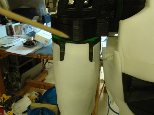
When omoplate is at default 10 position there is no gap between these two parts

See video for the omoplate movement:
https://inmoov.fr/wp-content/uploads/2015/10/MOV05330.mpg
##############################################################################
Setting « shoulder » servo and potentiometer to position 33 on a range of 0 to 180. It is not the default position for « rest » but this way, we can align the two servos seen from the back of InMoov.
To reach this value you may have to rotate slightly your potentiometer in it’s bracket.
See video for the shoulder movement:
https://inmoov.fr/wp-content/uploads/2015/10/MOV05329.mpg
##############################################################################
Setting « rotate » servo and potentiometer to default « Rest » position 90 on a range of 0 to 180.
Align the parts as shown on the pictures.
To reach this value you may have to rotate slightly your potentiometer in it’s bracket.
See video of the « rotate » servo movement:
https://inmoov.fr/wp-content/uploads/2015/10/MOV05328.mpg
OLDER TUTORIAL:
Assemble « PivGear » to « PivCenter »
It should turn in it smoothly but without backlash.
Using a fear amount of grease is a good idea.

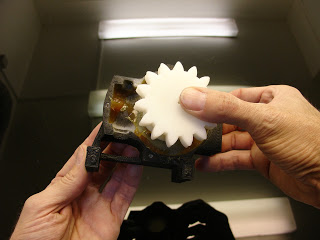
Ok, This section with green parts is the same than for the bicep so I re-used the pictures and changed the name of the parts. This picture is to show you what is the angle position of « PivCenterV1 » compared to « PivMitV1 ». Check the little rectangle hole where the potentiometer will go.

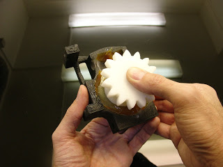
So keeping the same rotation angle, mount « PivmitV1 » to « PivgearV1 ».

I used clamps to make sure there wouldn’t be slack between all three parts during pre-screwing. Leave them like this, we will screw them definitly together in a further step.

Attach one servo to « PivcenterV1 ». For to do so: mount but don’t tight fit the white actuator wheel.

Once the servo is attached, you can tight the screw.
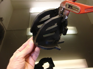
Clean up the support on « PivWormV1 »

Mount « PivWormV1 » to the actuator with 4 little screws, make sure they don’t come out behind the actuator, otherwise you have to cut them. I made it operate a few turns by plugging the servo on the Arduino. Then I cleaned up the dust created by the parts.

Before closing the case with « PivTitV1 », make sure you used a good amount of grease, every where on the gears. (sorry the servo is not mounted on this picture)
Mount the two « ConnectorV1 » to « RotTitV1 » and « PivMitV1 », making the junction between the bicep and the shoulder.
Glue with acetone all three parts together, and do it well, this is going to take a lot of pressure.
This is how they should be positionned. (sorry this picture is after everything is built)
Set « PivGearV1 » in this rotation angle to « PivMitV1 ». Here have a close look at angle of the hole of the potentiometer inside « PivGearV1 ». (sorry the screws of the next step are already mounted on this picture)
Use a longer screw to assemble « PivGearV1 » to « PivMitV1 » to « RotTitV1 »
Use a clamp to make sure there is no slack between the parts during mounting.
Then screw « PivGearV1 » to « PivMitV1 » on the sides and top.
Put together the two « ServoHolderV1 » and « ServoHolsterV1 »
Mount the assembly to « PivTitV1 ». Glue well with acetone, this is going to take pressure too, but make sure the « ServoHolsterV1 » can rotate freely.
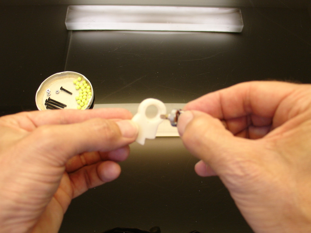
Set in the potentiometer into « PivPotentioV2 » and clip it as is.
Here make sure the welding for the right shoulder. Red wire being on top, yellow in the middle, and blue on the bottom. I used hot glue on the weldings to avoid short circuits.
Mount with screws »PistonClaviV2″ to the white wheel of your servo. set your servo into « ServoHolsterV1 » with screws.
Attach the complete arm to the shoulder parts.
In the back of the shoulder clip the first part of « PivPotHolderV2 » to « ClaviBackV1 »
Remove the two screws attaching the servo and put in place the second part of « PivPotHolderV2 ».
Use long screws to go through the servo holes. Fix the potentiometer in place as is.
You can see on this picture I used « arduinosupport » from
the hand to set my Board.
Fix the bolt to complete the attachement of thearm to the shoulder.
Connect the two ribbons to your NervoBoards respectively on Arm and Hand.
You are now set to GO for your first test. One thing you should keep in mind is that the servo actuating « PistonClavi » should stay between 0 and 80 position, if you go further it will certainly break. Now if you use InMoov service from Myrobotlab, this is already implemented to avoid breakage. Remember to do your test in a large space, and check your wires so they don’t get torn off.
Tip for testing: Personnaly, I test servo by servo each position before launching the whole shoulder. To do that I just unplug the servo cables that I don’t want to power on the Arm minibreakout board.
Go to STEP4 for to set up your default positions.